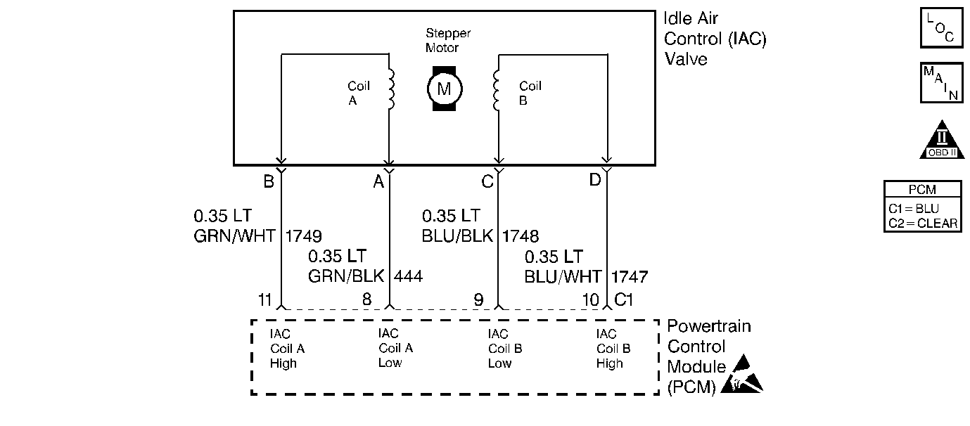
Circuit Description
This diagnostic test is used to determine if the Idle Air Control (IAC) system is maintaining the proper idle speed. The IAC system controls idle speed by allowing a certain amount of air to bypass the throttle body (the throttle plate is closed during idle) through the IAC valve. The PCM controlled IAC motor moves a pintle in and out of the IAC valve, thus varying the amount air entering the intake manifold. By varying the amount of air intake, different idle speeds can be achieved. When the pintle is in, the valve is closed and low idle speeds result. When the pintle is out, the valve is open and high idle speeds occur. If the engine idle speed is greater than the desired idle speed and all the test conditions are met, the PCM will cycle the IAC valve and expect to see a change in the MAF sensor reading. If no change occurs DTC P1509 is set.
Conditions for Running the DTC
| • | DTCs P0101, P0102, P0103, P0106, P0107, P0108, P0112, P0113, P0117, P0118, P0121, P0122, P0123, P0125, P0201, P0202, P0203, P0204, P0205, P0206, P0207, P0208 or P0502 not set. |
| • | P1370, P1371, P1406, and P1441 not testing. |
| • | PCM not checking EGR operation. |
| • | Ignition voltage between 10.5 and 15 volts. |
| • | BARO at least 65 kPa. |
| • | ECT is between -20°C (-4°F) and 110°C (230°F). |
| • | Engine running for at least 10 seconds. |
| • | PCM in Closed Loop fuel control. |
| • | MAF between 2 and 35 grams per second. |
| • | Actual idle speed greater than desired idle speed by at least 80 RPM. |
| • | DTC P0507 idle test has failed. |
| • | Vehicle speed between 30 and 45 MPH. |
| • | Commanded IAC position between 100 and 205 counts. |
| • | Throttle position varies less than 1 degree throughout the test. |
| • | Engine speed varies less than 75 RPM throughout the test. |
| • | A P/N to D/R or a D/R to P/N transition has not occured within the last 60 seconds. |
Conditions for Setting the DTC
MAF changes less than 1.5 grams per second during the 2 seconds that the IAC position was decreased.
Action Taken When the DTC Sets
| • | The PCM will illuminate the Malfunction Indicator Lamp (MIL) when the diagnostic runs and fails. |
| • | The PCM will record operating conditions at the time the diagnostic fails. This information will be stored in the Freeze Frame and Failure Records. |
Conditions for Clearing the MIL/DTC
| • | The PCM will turn the MIL OFF after three consecutive drive trips that the diagnostic runs and does not fail. |
| • | A Last Test Failed (current) DTC will clear when the diagnostic runs and does not fail. |
| • | A History DTC will clear after forty consecutive warm-up cycles with no failures of any emission related diagnostic test. |
| • | Use a scan tool to clear DTCs. |
| • | Interrupting PCM battery voltage may or may not clear DTCs. This practice is not recommended. Refer to Clearing Diagnostic Trouble Codes in PCM Description and Operation. |
Diagnostic Aids
Reviewing the Failure Rec. may help diagnose an intermittent failure by showing how long ago and under what conditions the DTC set.
Test Description
Number(s) below refer to the step number(s) on the Diagnostic Table.
Step | Action | Value(s) | Yes | No | ||||||||
|---|---|---|---|---|---|---|---|---|---|---|---|---|
1 | Did you perform the Powertrain On-Board Diagnostic (OBD) System Check? | -- | Go to Step 2 | |||||||||
Does the Engine Speed remain within the specified value of Desired Idle for each RPM command? | 50 RPM | Fault not present. Refer to Diagnostic Aids | Go to Step 3 | |||||||||
3 |
Does each node light cycle red and green (never OFF)? | -- | Go to Step 5 | Go to Step 4 | ||||||||
4 |
Was a problem found and repaired? | -- | Go to Step 8 | |||||||||
Visually/physically inspect for the following conditions:
Do any of the above require a repair? | -- | Refer to appropriate section for on-vehicle service. | Go to Step 6 | |||||||||
6 | Check for poor terminal contact at the IAC harness connector. Was a problem found and repaired? | -- | Go to Step 7 | |||||||||
7 | Replace the IAC valve. Refer to Idle Air Control Valve Replacement . Is the repair complete? | -- | -- | |||||||||
8 |
Was terminal contact repaired? | -- | Go to Step 9 | |||||||||
9 | Replace the PCM. Refer to Powertrain Control Module Replacement/Programming . Is the repair complete? | -- | -- |
