Torque Converter Clutch Pulse Width Modulated Solenoid Valve
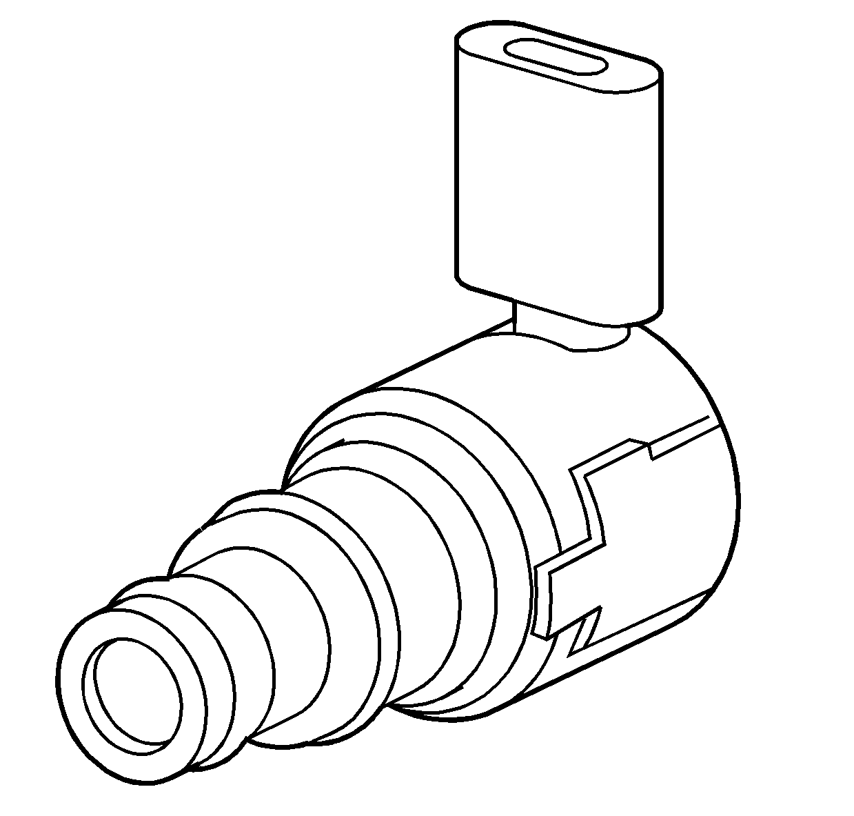
The torque converter clutch (TCC) solenoid valve is a three-port assembly which uses negative (-) duty cycle, pulse width modulation (PWM) to control the rate of TCC apply and release. The solenoid's ability to ramp apply and release pressures results in a smoother apply and release of the TCC in all conditions.
The TCC PWM solenoid valve is a normally closed valve, mounted to the upper control valve body and used to control the position of the TCC apply valve.
TCC PWM solenoid valve resistance should be 10-11 ohms when measured at 20°C (68°F). Resistance should be 13-15 ohms when measured at 100°C (212°F).
Transmission Pressure Control Solenoid Valve (Force Motor)
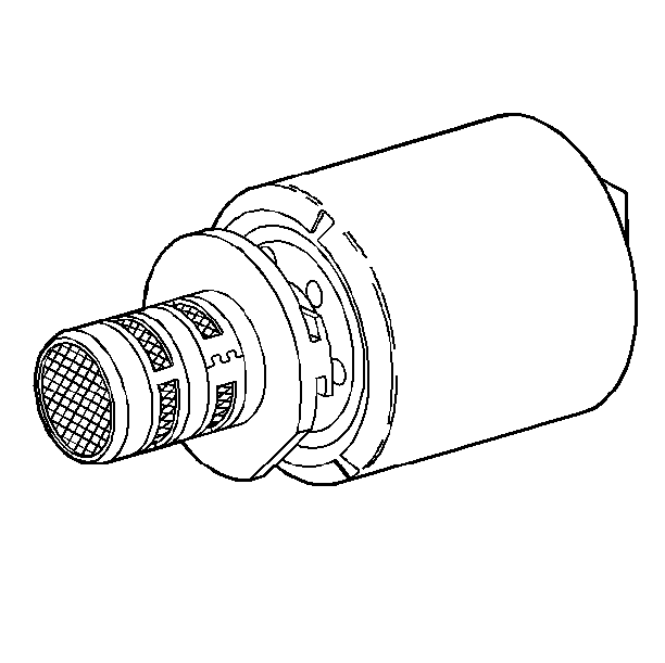
A transmission Pressure Control Solenoid Valve (PC Sol valve), also known as a force motor is a three-port, spool valve, electronic pressure regulator. The solenoid controls pressure based on a flow of current through its coil-winding. The solenoid controls main line pressure by moving a pressure regulator valve against spring pressure.
The position of the PC Sol. valve is controlled by a combination of two methods: high side control and low side control. One terminal of the solenoid receives a fixed frequency signal of 614.0 Hz. This signal varies in positive (+) duty cycle. This feed circuit is called Force HI.
The opposite terminal of the transmission pressure control solenoid is called Force LO. Force LO provides a ground for the solenoid.
This combination of Force HI and Force LO circuitry controls the actual current through the PC Sol. valve. This advanced control method assures instantaneous control of line pressure when changes occur in the TPS and adaptive learning.
The resistance on the PC Sol. valve should measure 3.0-7.0 ohms when measured at 20°-100°C (68°-212°F).
1-2 and 2-3 Shift Solenoid Valves
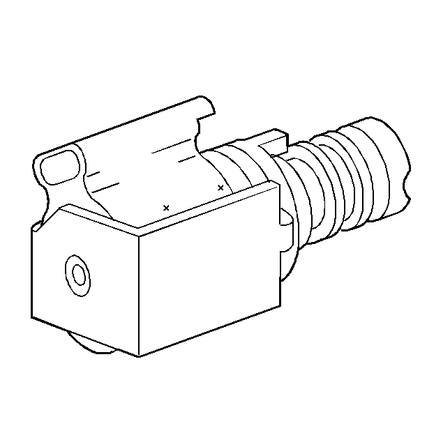
A shift solenoid valve is a two-port, feed-bleed device consisting of a coil/plunger-ball assembly. The solenoid assembly works with an orifice to pressurize the shift valve end chamber when voltage is applied to its coil. The controlled pressure then moves the shift valve against a spring causing a shift to occur. When voltage is no longer applied, the chamber opens to exhaust and the opposite shift valve action occurs. Shift solenoids eliminate the need for TV and governor pressures to control shift valve operation.
The 4T80-E transmission uses two shift solenoid valves: the 1-2 and 2-3, which are attached to the lower valve body.
Important: If both solenoids lose power, only Second gear will result.
Shift solenoid resistance should measure 19-24 ohms when measured at 20°C (68°F). Resistance should measure 24-31 ohms when measured at 100°C (212°F). Shift solenoid current flow should not exceed 0.75 amps. The shift solenoid valve should energize at a voltage of 7.5 volts or more, measured across the terminals. The shift solenoid valve should de-energize when voltage is one volt or less.
Automatic Transmission Fluid Pressure Manual Valve Position Switch Assembly
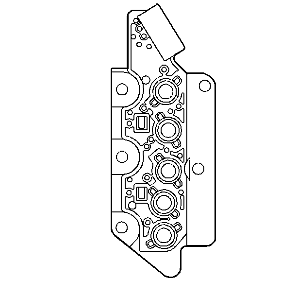
The automatic transmission fluid pressure (TFP) manual valve position switch assembly contains five pressure switch assemblies. These assemblies are normally open. The pressure switch assemblies are used to indicate the manual valve range of the transmission through the use of a binary code.
For each of the three PCM signal lines, the pressure switch produces either an open or a ground, depending on whether pressure is applied to the switch. The TFP manual valve position switch is attached to the lower control valve body. The sequence of open and closed switches is used by the PCM to determine actual manual valve position. This input controls line pressure, the TCC and the shift solenoids.
In order to monitor TFP manual valve position switch operation, the PCM compares actual voltage values to a combination table stored in its memory. If the PCM does not recognize the TFP manual valve position switch sequence (voltage sequence) for the range selected, a DTC P1810 will result.
| • | Pin N is mode A |
| • | Pin R is mode B |
| • | Pin P is mode C |
Range Indicator | Fluid Pressure Present | Circuit/Mode | ||||||||||||||
|---|---|---|---|---|---|---|---|---|---|---|---|---|---|---|---|---|
| REV | D4 | PRND4 | PRND43 | LO | A | B | C | ||||||||
Park | 0 | 0 | 1 | 1 | 0 | OFF | ON | OFF | ||||||||
Reverse | 1 | 0 | 1 | 1 | 0 | ON | ON | OFF | ||||||||
Neutral | 0 | 0 | 1 | 1 | 0 | OFF | ON | OFF | ||||||||
D4 | 0 | 1 | 1 | 1 | 0 | OFF | ON | ON | ||||||||
D3 | 0 | 1 | 0 | 1 | 0 | OFF | OFF | ON | ||||||||
D2 | 0 | 1 | 0 | 0 | 0 | OFF | OFF | OFF | ||||||||
LO | 0 | 1 | 0 | 0 | 1 | ON | OFF | OFF | ||||||||
| ||||||||||||||||
Seven valid combinations and two invalid combinations are available from the TFP manual valve position switch. Valid combinations for circuits A, B, and C are shown in the Fluid Pressure and Circuit Combination table. The invalid combinations displayed on the Scan Tool are A = ON, B = ON, C = ON or A = ON, B = OFF, C = ON.
Vehicle Speed Sensor
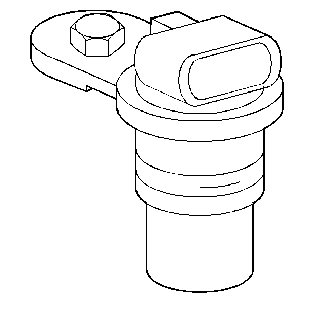
The vehicle speed sensor (VSS) is mounted on the transmission case extension facing toward the right wheel. This sensor consists of a permanent magnet surrounded by a coil of wire. The sensor mounts into the extension and maintains a slight air gap (0.045-0.109 in) between itself and a rotor which is located on the differential. The VSS measures the speed of the rotor, which contains 31 teeth. As the differential rotates, an AC signal is induced in the VSS. The AC signal varies in frequency and voltage output:
| • | Low speed = low Hz and voltage amplitude |
| • | High speed = high Hz and voltage amplitude |
This input is used for TCC, line pressure, shift timing and torque management controls.
Sensor resistance should be 1300-1950 ohms when measured at 20-100°C (68-212°F). Output voltage varies with speed from a minimum of 0.5 volts AC at 100 RPM, to more than 100 volts AC at 8000 RPM.
Automatic Transmission Input (Shaft) Speed Sensor
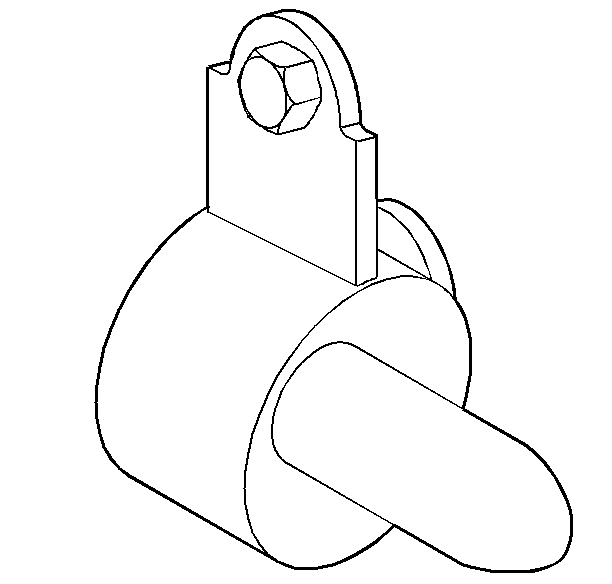
The Automatic Transmission Input (Shaft) Speed sensor is mounted in the case cover facing the drive sprocket. The sensor consists of a permanent magnet surrounded by a coil of wire. The sensor mounts into the case and maintains a slight air gap (0.045-0.109 in.) between itself and the drive sprocket. An AC voltage signal is induced in the input sensor by rotating the drive sprocket, which contains 39 teeth cut in its outside diameter. The voltage output and frequency varies with housing speed:
| • | Low speed = low Hz and voltage amplitude |
| • | High speed = high Hz and voltage amplitude |
Inside the PCM, this analog signal changes to a digital signal. The processor then compares this digital signal to a fixed clock signal within the PCM in order to determine the actual turbine speed. The PCM uses input speed for control of line pressure and speed calculation.
Sensor resistance should be 1300-1950 ohms when measured at 20°-100°C (68°-212°F). Output voltage will vary with speed from a minimum of 0.5 volts AC at 100 RPM, to more than 100 volts AC at 8000 RPM.
Automatic Transmission Fluid Temperature Sensor
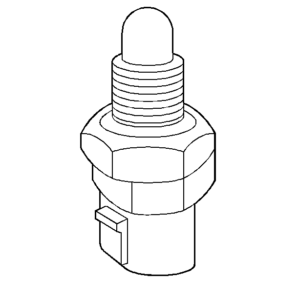
The automatic transmission fluid temperature (TFT) sensor controls TCC and line pressure. The TFT sensor attaches to the upper control valve assembly. The TFT signals the PCM regarding transmission fluid temperature. The sensor is a negative temperature coefficient thermistor which receives a five volt signal from the PCM.
When the temperature is cold, the sensor resistance is high; therefore, the PCM sees a high signal voltage. As the fluid warms, the sensor resistance decreases, the voltage drop across the sensor becomes lower.
The TFT sensor may be tested with an ohmmeter across pin terminals L and M of the 20-way transmission connector. Nominal ohm readings at specified temperatures are given in voltage levels at the PCM. Refer to Temperature Versus Resistance .
The temperature sensor mode operates in the following two ways:
| • | Hot mode enable: Above 130°C (266°F) - TCC ON in 3rd gear at 48 km/h (30 mph) with 0-10 degree throttle angle; and 4th gear at 63 km/h (39 mph) with 0-10 degree throttle angle. This reduces transmission temperature by decreasing the amount of heat generated in the torque converter. It also provides maximum cooling by routing transmission fluid directly to the transmission cooler in the engine radiator. |
| • | Super hot mode disable on the 275 HP RPO LD8 ENGINE: Above 140°C (284°F) - TCC OFF with 4th gear inhibited. Super hot is a condition where a hot engine adds heat to the transmission through the transmission cooler. By inhibiting TCC and 4th gear operation, the engine works under less load. This reduces the heat added to the transmission fluid by the transmission cooler. As both the engine and the transmission cool off, TCC and 4th gear are permitted again. |
A PCM internal shunt circuit comes into play as the temperature increases beyond 50°C (122°F). As the temperature decreases, the internal shunt comes out at 40°C (104°F). There is a 10°C (18°F) overlap.
