Removal Procedure
Caution: This vehicle is equipped with a Supplemental Inflatable Restraint (SIR) System. Failure to follow the correct procedure could cause the following conditions:
| • | Unnecessary SIR system repairs |
| • | Refer to SIR Component Views in order to determine if you are performing service on or near the SIR components or the SIR wiring. |
| • | If you are performing service on or near the SIR components or the SIR wiring, disable the SIR system. Refer to Disabling the SIR System. |
Caution: In order to prevent SIR deployment, personal injury, or unnecessary SIR system repairs, do not strike the door or the door pillar in the area of the side impact sensor (SIS). Turn OFF the ignition and remove the key when performing service in the area of the SIS.
- Disable the SIR system. Refer to
Disabling the SIR System
.
- Remove the lock assembly. Refer to
Door Lock Replacement
.

- Remove the 2 TORX®
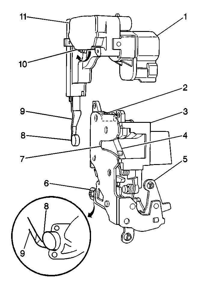
fasteners retaining the actuator (1) to the lock assembly.
- Remove the actuator (1).
Installation Procedure

Important: Before installing the new actuator, the latch (4) must be in the full
open position. The teeth on the lock actuator (10) must be pushed fully toward
the actuator arm in order to prevent damage to the lock assembly after
the assembly is operated.
- Position the plastic teeth (10) of the lock switch (11).
Push the teeth fully toward the actuator arm (9) in order to mesh the
lock switch teeth (10) with the teeth on the lock assembly
when installed.
- Position the new actuator onto the lock assembly.
- Verify that the actuating arm rubber bumper (8) is on the
actuating arm (9).
- Install the following components into the locking lever:
- Align the lock switch teeth to the gear tooth fork bolt (2).
- Align the fastener holes.
Notice: Use the correct fastener in the correct location. Replacement fasteners
must be the correct part number for that application. Fasteners requiring
replacement or fasteners requiring the use of thread locking compound or sealant
are identified in the service procedure. Do not use paints, lubricants, or
corrosion inhibitors on fasteners or fastener joint surfaces unless specified.
These coatings affect fastener torque and joint clamping force and may damage
the fastener. Use the correct tightening sequence and specifications when
installing fasteners in order to avoid damage to parts and systems.
- Install the 2 TORX®
fasteners.
Tighten
Tighten the fasteners to 8 N·m (71 lb in).

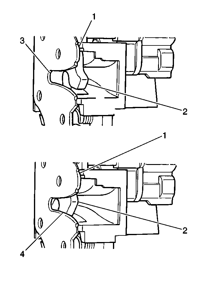
- Manually operate the lock
assembly (1). Push inward on the fork bolt (2) until the fork
bolt clicks from a partially closed position (3) into a fully
closed position (4).
Ensure that the lock fully closes without any interference.
- Connect the electrical connections.
- Test the operation of the following components:
- Install the lock assembly (1).
- Ensure that the lock carrier meets the following conditions:


