Door Lock Switch Replacement DeVille
Removal Procedure
Caution: This vehicle is equipped with a Supplemental Inflatable Restraint (SIR) System. Failure to follow the correct procedure could cause the following conditions:
• Air bag deployment • Personal injury • Unnecessary SIR system repairs • Refer to SIR Component Views in order to determine if you are performing service on or near the SIR components or the SIR wiring. • If you are performing service on or near the SIR components or the SIR wiring, disable the SIR system. Refer to Disabling the SIR System.
Caution: In order to prevent SIR deployment, personal injury, or unnecessary SIR system repairs, do not strike the door or the door pillar in the area of the side impact sensor (SIS). Turn OFF the ignition and remove the key when performing service in the area of the SIS.
- Disable the SIR system. Refer to Disabling the SIR System .
- Remove the door trim panel. Refer to Front Side Door Trim Panel Replacement or Rear Side Door Trim Panel Replacement .
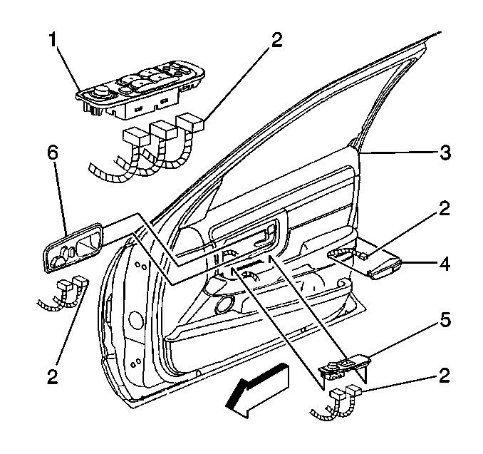
- Disconnect the electrical connectors (2).
- From the backside of the trim panel , gently pry the tabs in order to release the lock switch plate from the trim panel.
- Remove the lock switch from the switch plate.

Installation Procedure
- Install the lock switch into the switch plate. Ensure that the tabs engage in order to retain the lock switch to the switch plate.
- Connect the electrical connectors (2).
- Enable the SIR system. Refer to Enabling the SIR System .
- Install the door trim panel. Refer to Front Side Door Trim Panel Replacement or Rear Side Door Trim Panel Replacement .

Door Lock Switch Replacement Eldorado
Removal Procedure
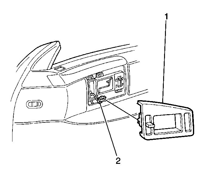
- Carefully pull the trim plate (1) from the trim panel.
- Disconnect the electrical connector (2) from the lock switch.
- Remove the door lock switch.

Installation Procedure
- Connect the electrical connector (2).
- Position the lock switch plate (1) on the trim panel.
- Press the lock switch plate into the trim panel.

