Radio Replacement Eldorado and DeVille w/D55
Removal Procedure
- Remove the console trim plate. Refer to
Console Front Trim Plate Replacement
in Instrument Panel, Gauges, and Console.
- Remove the ashtray assembly. Refer to
Ashtray Replacement
in Instrument Panel,
Gauges, and Console.
- Remove the driver information center switch (DIS). Refer to
Driver Information Display Switch Replacement
in Instrument Panel, Gauges, and Console.
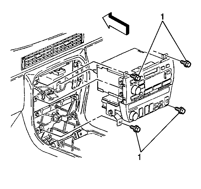
- Remove the fasteners (1)
from the radio/heater/AC control assembly.
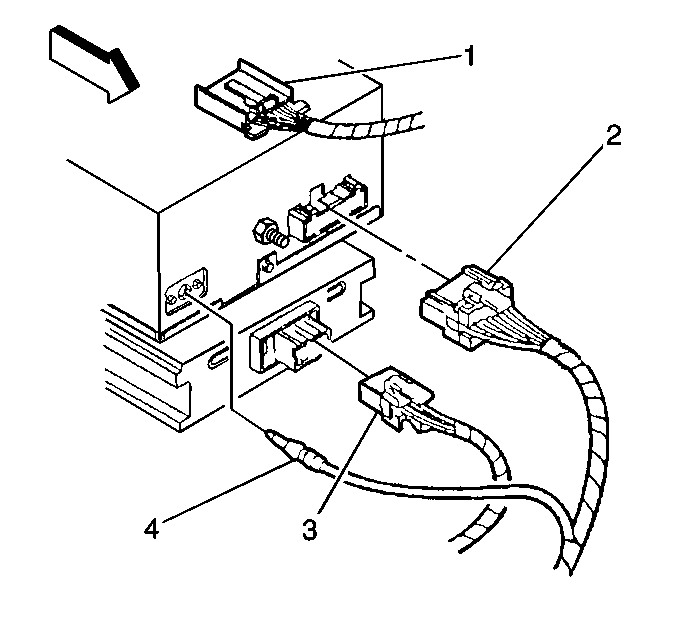
- Disconnect the following
components:
| • | The electrical connectors (1, 2, 3) |
| • | The antenna coax cable (4) |
- Remove the radio.
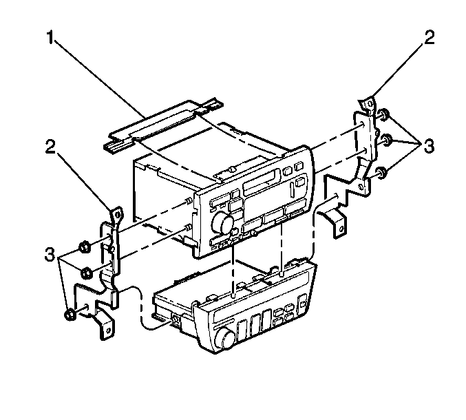
- If you are using an exchange
radio, perform the following additional steps:
| 7.1. | Remove the bracket fasteners (3). |
| 7.2. | Remove the 2 brackets (2) from the sides of the radio control
head. |
| 7.3. | Remove one 16 mm (0.63 in) plastic locating pin
and clip stud from the rear of the control head. |
| 7.4. | Remove the driver information display switch and bracket (1). |
Installation Procedure

- If you are using an exchange
radio, perform the following additional steps:
| 1.1. | Install the driver information display switch bracket (1). |
| 1.2. | Install one 16 mm (0.63 in) plastic locating pin
and clip stud to the rear of the control head. |
| 1.3. | Install the 2 brackets (2) to the sides of the radio
control head. |
Notice: Use the correct fastener in the correct location. Replacement fasteners
must be the correct part number for that application. Fasteners requiring
replacement or fasteners requiring the use of thread locking compound or sealant
are identified in the service procedure. Do not use paints, lubricants, or
corrosion inhibitors on fasteners or fastener joint surfaces unless specified.
These coatings affect fastener torque and joint clamping force and may damage
the fastener. Use the correct tightening sequence and specifications when
installing fasteners in order to avoid damage to parts and systems.
| 1.4. | Install the mounting
bracket fasteners. |
Tighten
Tighten the fasteners to 6 N·m (53 lb in).

- Connect the harness connectors (1,
2, 3).
- Connect the antenna coax cable (4).

- Install the radio/heater/AC
control assembly.
- Install the fasteners (1).
Tighten
Tighten the fasteners to 2 N·m (18 lb in).
- Install the DIS into the console opening. Refer to
Driver Information Display Switch Replacement
in
Instrument Panel, Gauges, and Console.
- Install the ashtray. Refer to
Ashtray Replacement
in Instrument Panel,
Gauges, and Console.
- Install the console trim plate. Refer to
Console Front Trim Plate Replacement
in Instrument Panel, Gauges, and Console.
Radio Replacement Deville w/o D55
Removal Procedure
- Remove the radio trim plate. Refer to
Instrument Panel Lower Center Trim Replacement
in Instrument Panel, Gauges, and Console.
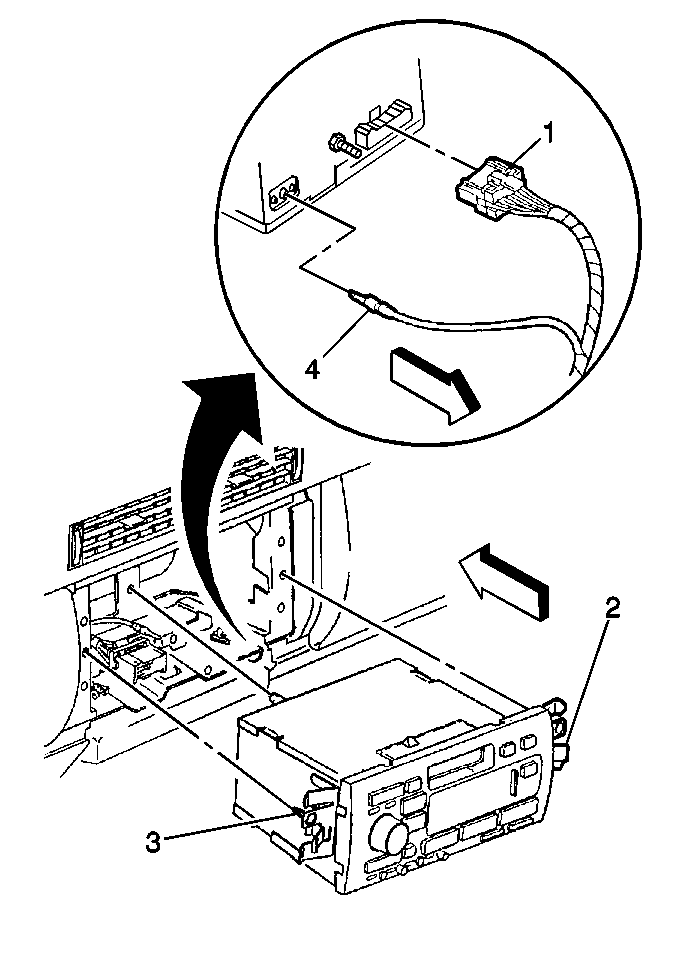
- Push inward on the tabs (2) on the side of the radio.
Pull out the radio.
- Remove the radio control head.
- Disconnect the following components:
| • | The harness connector (1) |
- Remove the radio.
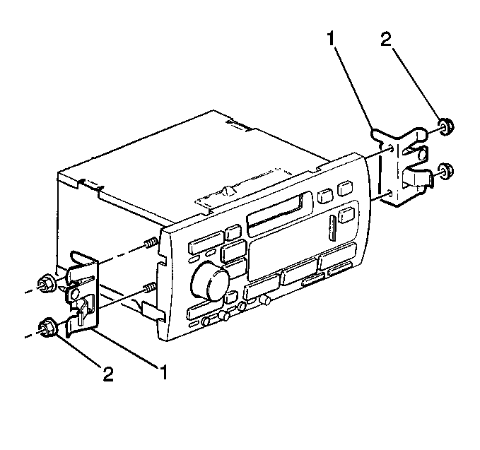
- If using an exchange radio,
perform the following additional steps:
| 6.1. | Remove the 2 brackets (1) from the sides of the
radio control head. |
| 6.2. | Remove one 16 mm (0.63 in) plastic locating pin
and clip stud from the rear of the control head. |
Installation Procedure

- If using an exchange radio,
perform the following additional steps:
| 1.1. | Install one 16 mm (0.63 in) plastic locating pin
and clip stud to the rear of the control head. |
| 1.2. | Install the 2 brackets (1) to the sides of the radio
control head. |
Notice: Use the correct fastener in the correct location. Replacement fasteners
must be the correct part number for that application. Fasteners requiring
replacement or fasteners requiring the use of thread locking compound or sealant
are identified in the service procedure. Do not use paints, lubricants, or
corrosion inhibitors on fasteners or fastener joint surfaces unless specified.
These coatings affect fastener torque and joint clamping force and may damage
the fastener. Use the correct tightening sequence and specifications when
installing fasteners in order to avoid damage to parts and systems.
| 1.3. | Install the mounting
bracket fasteners. |
Tighten
Tighten the fasteners to 5 N·m (44 lb in).

- Connect the following components:
| • | The radio harness connector (1) |
| • | The antenna coax cable (4) |
- Guide the radio into the instrument panel.
Align the pin on the rear of the radio.
Push in on the pin until the lock tabs catch.
- Install the radio trim plate. Refer to
Instrument Panel Lower Center Trim Replacement
in Instrument Panel, Gauges, and Console.


