Engine Coolant Temperature (ECT) Sensor
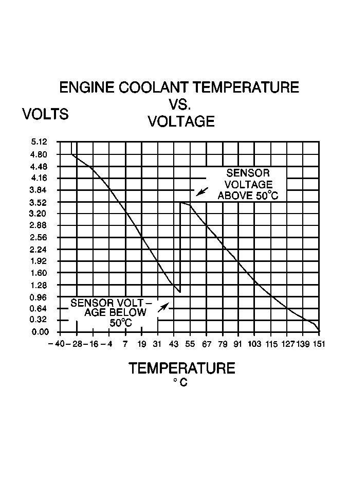
The ECT sensor is a thermistor (a resistor that changes value due to temperature) mounted in the engine coolant flow. High coolant temperatures result in low resistance and low temperatures result in high resistance. The PCM provides a 5 volt reference signal and a ground to the ECT sensor, and it measures the voltage signal as it changes due to the sensors resistance. A high coolant temperature will result in low signal voltage (near 0 volt) and low coolant temperature will result in high signal voltage (near 5 volts).
The ECT sensor circuit uses two different temperature sensing circuits for two temperature ranges -- below 50°C (122°F) and above 50°C (122°F). The PCM will shift between a high resistance circuit for low temperatures and a low resistance circuit for high temperatures.
Intake Air Temperature (IAT) Sensor
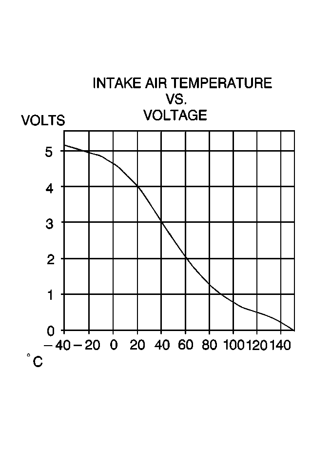
The IAT sensor is a thermistor (a resistor that changes value with temperature) mounted in the intake air stream and it measures changes in the temperature of air entering the engine. High air temperatures result in low resistance and low air temperatures result in high resistance. The PCM provides a 5 volt reference signal and a ground to the IAT sensor. The PCM measures the voltage changes in the signal due to the sensors resistance. A high air temperature will result in low signal voltage (near 0 volt) to the PCM and low air temperature will result in high signal voltage (near 5 volt).
Manifold Absolute Pressure (MAP) Sensor
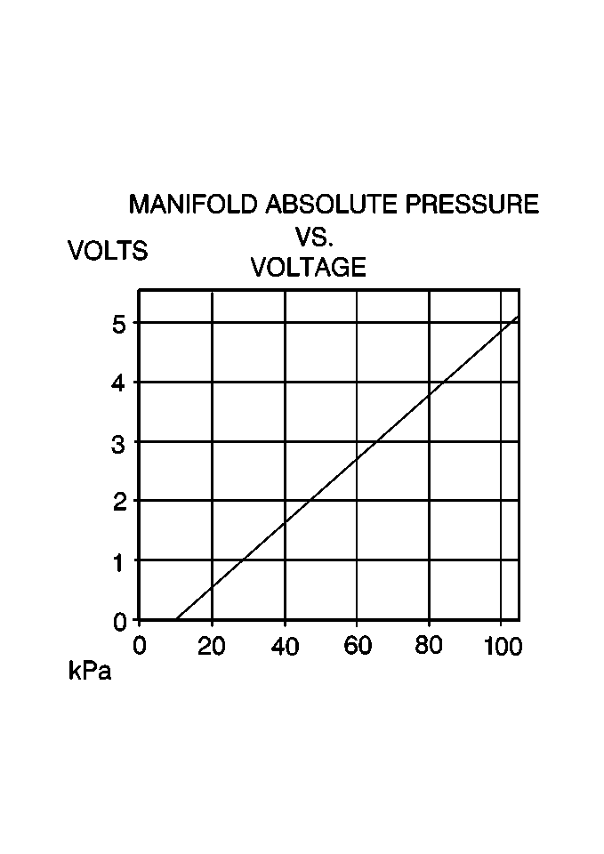
The MAP sensor is a potentiometer that is mounted on the intake manifold and measures the changes in intake manifold pressure due to engine speed and load changes. The PCM supplies a 5 volt reference signal and a ground to the MAP sensor and the sensor in turn sends a voltage signal to the PCM. As manifold pressure increases (vacuum decreases), the voltage signal increases and as manifold pressure decreases (vacuum increases), the voltage signal decreases. A high pressure signal will be close to 5 volts and a low pressure signal will be close to 0 volt.
Mass Air Flow (MAF) Sensor
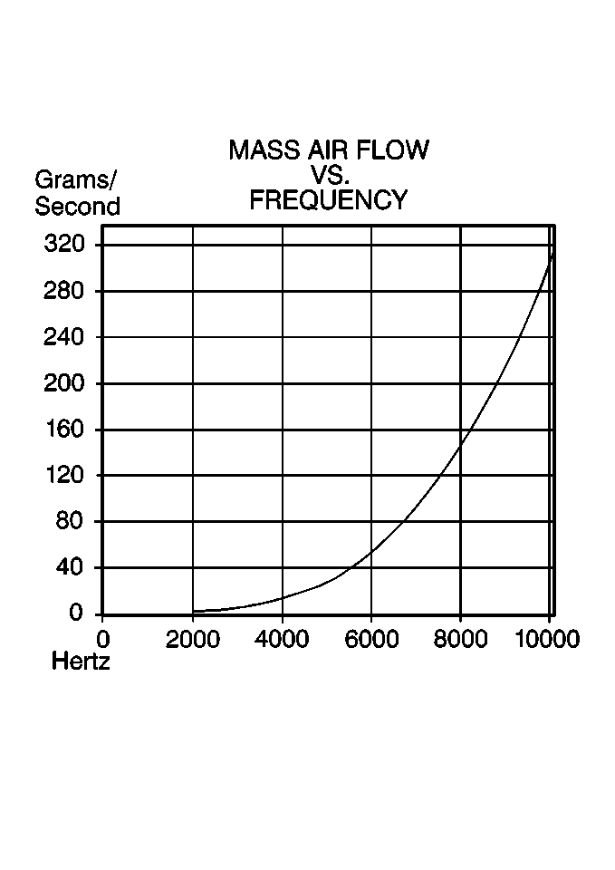
The MAF sensor is an electronic device that measures air flow into the intake manifold. The MAF sensor is mounted to the throttle body. The MAF sensor is supplied battery voltage and a ground. The MAF sensor in turn sends a frequency signal to the PCM. As air flow increases, the signal frequency increases and as air flow decreases, the signal frequency decreases. A high flow signal will be close to 9000 Hertz and a low flow signal will be close to 2000 Hertz.
Throttle Position (TP) Sensor
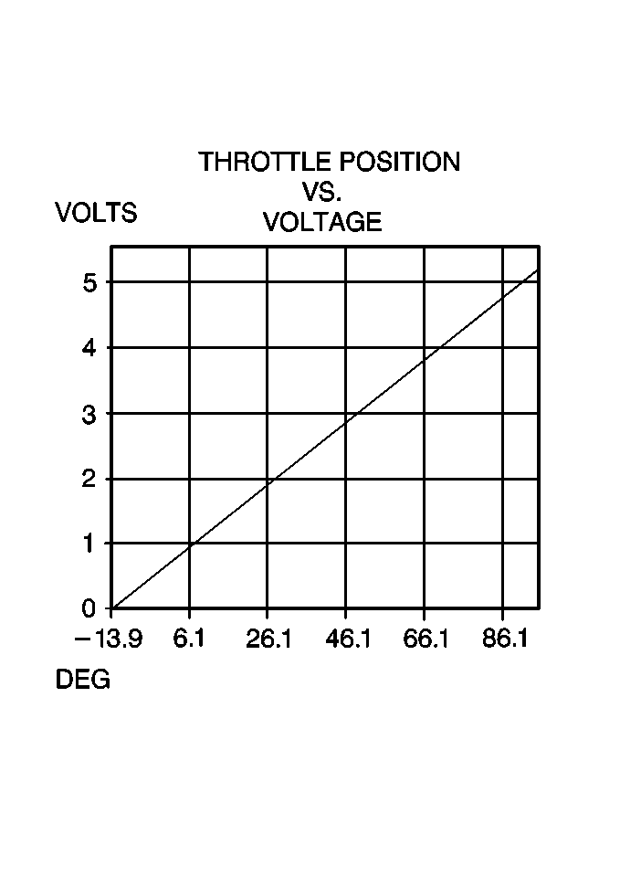
The TP sensor is a potentiometer that is mounted on the throttle body to measure changes in throttle valve angle. The PCM provides a 5 volt reference signal and a ground to the TP sensor and the sensor in turn sends a voltage signal representing throttle position back to the PCM. As the throttle angle increases, the voltage signal increases and as the throttle angle decreases the voltage signal decreases. A closed throttle angle will result in a voltage signal near 0 and wide open throttle will produce a signal near 5 volts.
Heated Oxygen Sensors (HO2S)
Important: Only early model year production are equipped with a Pre-Converter (B1S2) Heated Oxygen Sensor (HO2S). If equipped, this HO2S is connected to the PCM and vehicle electrical system but is no longer monitored or diagnosed.
The three or four oxygen sensors are mounted in the exhaust system where they monitor the oxygen content in the exhaust stream. There is an oxygen sensor mounted in each exhaust manifold and one on the downstream end of the catalytic converter. Some early production vehicles also have an oxygen sensor located at the front of the catalytic converter (Pre-converter). The oxygen sensor located in the front exhaust manifold is the Bank 2 Sensor 1 (Front bank) sensor. The oxygen sensor located in the rear exhaust manifold is the Bank 1 Sensor 1 (Rear) sensor. The oxygen sensor located in the Y-pipe ahead of the catalytic converter is the Bank 1 Sensor 2 (Pre-converter) sensor. The oxygen sensor located in the catalytic converter outlet is the Bank 1 Sensor 3 (Post-converter) sensor.
An oxygen sensor acts like a battery because it creates its own signal voltage once it reaches operating temperature. This voltage is produced when the oxygen content in the exhaust stream is different than the oxygen content in the atmosphere. A lean condition (high oxygen content in exhaust) will produce a low voltage (near 0 volt) and a rich condition (low oxygen content in exhaust) will produce a high voltage (near one volt). The PCM provides a reference signal voltage (0.45 volt) and a ground to the sensor. The PCM reference voltage is necessary because the oxygen sensors do not provide their own voltage until they reach operating temperature.
The oxygen sensors also incorporate a heating element inside of the sensor housing. This heating element is energized with the ignition On and allows the sensors to reach operating temperatures quickly. The PCM can then use oxygen sensor information sooner after engine startup.
The PCM uses oxygen sensor information during Closed Loop operation to constantly adjust fuel control to reduce exhaust emissions. Because the oxygen sensors provide information sooner after engine startup, exhaust emissions are reduced. Faulty oxygen sensors will cause various driveability conditions and will set a DTC.
Knock Sensor
Varying octane levels in gasoline can cause detonation in high performance engines. Detonation is sometimes called spark knock. Spark knock causes the pistons and rings to vibrate and rattle producing the spark knocking sound.
To control spark knock a Knock Sensor (KS) is used. This system is designed to retard spark timing to reduce spark knock in the engine. This allows the engine to use maximum spark advance to improve driveability and to improve fuel economy.
The Knock Sensor (KS) system has two major components:
| • | The KS module. |
| • | The Knock Sensor (KS). |
The knock sensor is mounted into the engine block under the intake manifold. The knock sensor produces an AC voltage which increases with the severity of the knock. This signal voltage inputs to the Powertrain Control Module (PCM). The PCM then adjusts the Ignition Control (IC) to reduce spark knocking.
EGR Pintle Position Sensor
The PCM monitors the EGR valve pintle position input to ensure that the valve responds properly to commands from the PCM and to detect a fault if the pintle position sensor and control circuits are open or shorted. If the PCM detects a pintle position signal voltage outside the normal range of the pintle position sensor, or a signal voltage than is not within a tolerance considered acceptable for proper EGR system operation, the PCM will set a DTC.
EVAP Fuel Tank Pressure Sensor
The EVAP Fuel Tank Pressure Sensor is mounted to the Modular Fuel Sender assembly.
The EVAP Pressure sensor is a sensor that changes resistance based upon fuel tank pressure (or vacuum). A vacuum is considered negative pressure.
The PCM provides a 5 volt reference and ground. The EVAP Pressure sensor signal varies between ground and 5 volts as fuel tank pressure varies. As pressure decreases (negative pressure, or vacuum), voltage increases. As pressure increases, voltage decreases (positive pressure, low voltage). The PCM uses the EVAP Pressure sensor values as an indicator of EVAP system efficiency.
Vehicle Speed Sensor (VSS)
The VSS is a pulse generator mounted in the transaxle. A reluctor ring rotates near a magnetic pickup which produces a varying voltage signal in the pickup coil. This voltage signal varies in proportion to vehicle speed and is sent to the PCM, where it is converted to mph.
The PCM uses VSS information for fuel economy calculations, cruise control, idle speed control, transaxle shifts, and to control fuel under certain conditions. A faulty VSS may cause various transaxle and engine driveability conditions and will set a PCM DTC.
Brake Switches
This vehicle is equipped with two brake switches each containing multiple sets of contacts and performing several functions. Both switches are located under the left hand side of the I/P on the brake pedal support.
Torque Converter Clutch (TCC) Brake Switch
The Torque Converter Clutch (TCC) Brake Switch contains two sets of (normally closed) electrical contacts referred to as the Torque Converter Clutch (TCC) Brake and Extended Travel Brake Switch contacts. The TCC brake switch contacts provide brake status to the PCM for torque converter clutch control. The extended travel brake switch contacts are used in Torque Management to determine whether the brakes are applied.
Stop/BTSI/Cruise Brake Switch
The Stop/BTSI/Cruise Brake Switch contains three sets of electrical contacts. Two sets of contacts are normally closed and one set is normally open. The one normally open set of contacts is referred to as the stop lamp switch contacts and supplies power to the stop lamps when the brakes are applied. One set of normally closed contacts is referred to as the BTSI brake switch contacts and supplies power to the BTSI solenoid when the brakes are not applied. The other normally closed set of contacts is referred to as the cruise brake switch contacts and is used to disengage cruise when the brakes are applied.
Power Steering Pressure (PSP) Switch
The power steering pressure switch is located on the power steering pressure hose between the power steering pump and rack and pinion gear. The power steering pressure switch is normally closed and provides a battery voltage signal to the PCM with no power steering load. When power steering pressure increases to a calibrated level due to steering load (such as full steering lock), the switch opens and causes the signal voltage to the PCM to drop to 0 volts.
The PCM uses the power steering pressure switch signal for idle speed control during high steering loads to maintain a stable idle. A shorted power steering pressure switch may cause a stumble or stall during steering loads and an open switch should set a PCM DTC.
SMCC Cruise Control Engaged Input
The stepper motor cruise control module sends the cruise status input to the PCM to indicate when cruise control is engaged. The PCM monitors the cruise status signal while commanding cruise to be disengaged via the cruise inhibit circuit. Any of the following conditions may cause the PCM to inhibit cruise control operation:
| • | Engine not running long enough for cruise control operation. |
| • | Transaxle range inputs indicate park, neutral, low, or reverse gear selected. |
| • | Engine speed is too high or too low. |
| • | Vehicle speed is too high or too low. |
| • | Traction is active. |
| • | Vehicle acceleration or deceleration rate is too high. |
