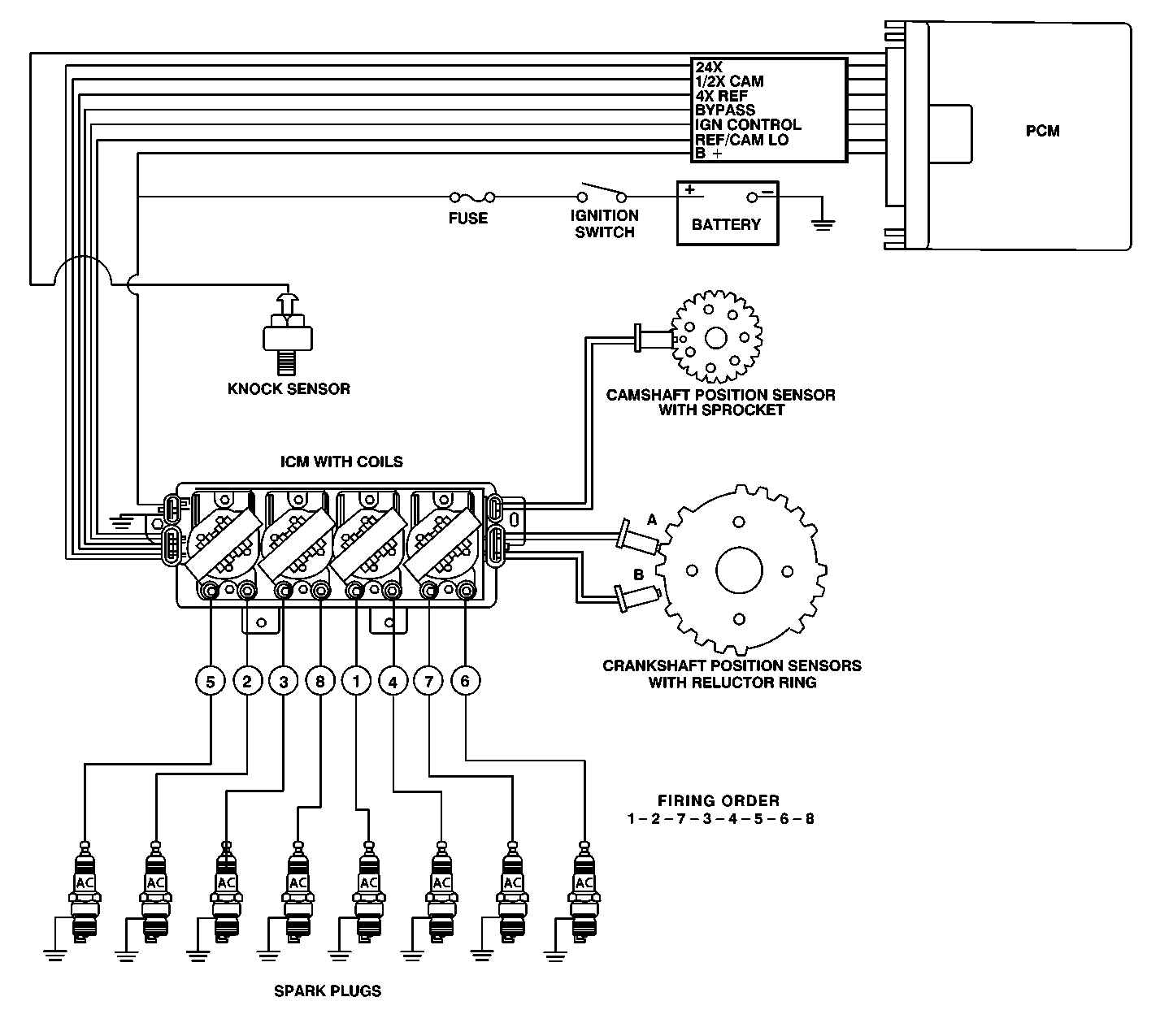
This Powertrains Ignition
Control System controls fuel combustion by providing a spark to ignite the
compressed air/fuel mixture in each cylinder at the correct time. This ignition
control system has several advantages over a mechanical distributor ignition
system.
| • | No moving parts to wear out. |
| • | No mechanical load on the engine. |
| • | Elimination of mechanical timing adjustments. |
| • | Located for easier service and improved reliability. |
| • | Improved high engine speed performance. |
The Ignition Control System consists of the following components:
| • | Two crankshaft position sensors (A and B). |
| • | Crankshaft reluctor ring. |
| • | Camshaft position sensor. |
| • | Ignition control module. |
| • | 4 separate ignition coils. |
| • | Eight spark plug wires and conduit. |
| • | Powertrain Control Module (PCM). |
System Operation
The Ignition Control System does not use a conventional distributor
or a single ignition coil. In this ignition system, both ends of each of the
four ignition coils are connected to a spark plug. Each coil is connected
with spark plugs on companion cylinders, i.e., on top dead center at the
same time (1-4, 2-5, 6-7, and 3-8). One cylinder
is on its compression stroke when the other one is on its exhaust stroke.
When the coil discharges, both plugs fire at the same time by using
the engine block to complete the electrical circuit. The cylinder on the compression
stroke is called the event cylinder and the one on the exhaust stroke is
the waste cylinder. The two cylinders share the energy available from the
ignition coil to fire both spark plugs. This method of ignition is called
waste spark ignition.
Since the polarity of the ignition coil primary and secondary windings
does not change, one spark plug always fires with a forward current (center
electrode to ground electrode) and its companion plug fires with a reverse
current (ground electrode to center electrode). This is different from a
conventional distributor ignition system that fires all the plugs with the
same forward current flow.
It is possible for one spark plug to fire even though a plug wire from
the same coil may be disconnected from its companion spark plug. The disconnected
plug wire acts as one plate of a capacitor and the engine block acts as the
other plate. These two capacitor plates are charged as a spark first jumps
across the gap of the connected spark plug. The plates are then discharged
as the energy is dissipated as the spark continues. Voltage requirements
are very high with an open spark plug or wire. The ignition coil may have
enough reserve energy to fire the connected plug at idle, but possibly not
under some engine load conditions. A more noticeable misfire may be evident
under load; both spark plugs may then not fire.
Crankshaft Position Sensors and Reluctor Ring
The two crankshaft sensors are located on the front bank (BANK 2) of
the engine block between cylinders 4 and 6. Crankshaft position A sensor is
located in the upper crankcase and crankshaft position B sensor is located
in the lower crankcase. Both sensors extend into the crankcase and are sealed
to the engine block with O-rings. The crankshaft position sensors are not
adjustable.
The magnetic crankshaft position sensors operate similar to the pickup
coil in a distributor. When a piece of steel (called a reluctor) is repeatedly
moved over the sensor, a voltage will be created by the sensor that appears
to go On-Off-On-Off-On-Off. This On-Off
signal is also similar to the signal that a set of breaker points in a distributor
would generate as the distributor shaft turned and the points opened and
closed.
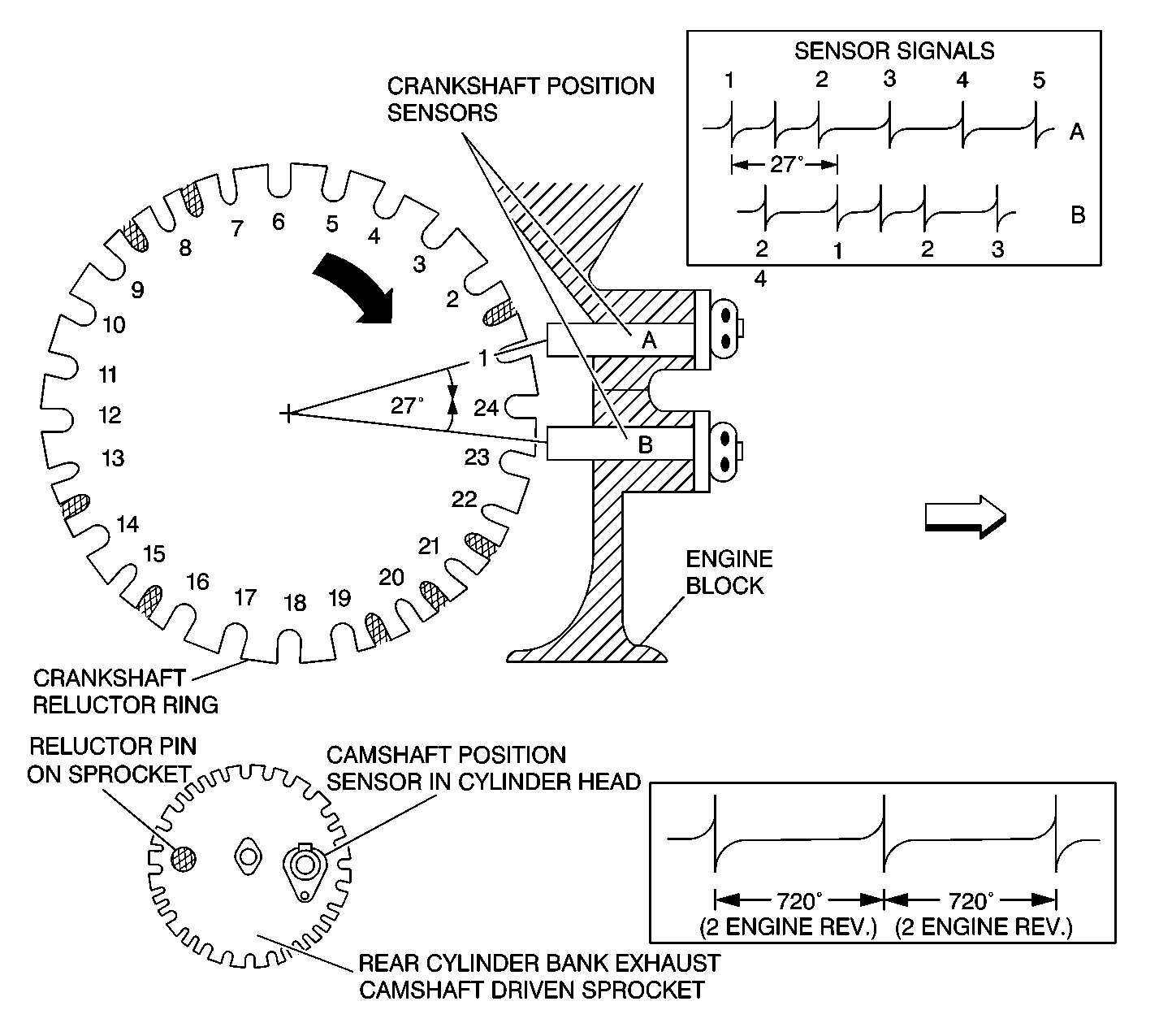
The reluctor ring is cast onto the crankshaft between the #3 and #4
main bearing journals. The reluctor ring has 24 evenly spaced notches or air
gaps and an additional 8 unevenly spaced notches for a total of 32.
As the crankshaft makes one complete revolution, both the A and B sensors
will produce 32 On-Off pulses per revolution. In addition, the A sensor
is positioned 27 degrees of crankshaft revolution before the B sensor. This
creates a unique pattern of On-Off pulses sent to the ignition control
module so that it can recognize crankshaft position.
Camshaft Sensor
The camshaft position sensor is located on the rear cylinder bank (BANK
1) in front of the exhaust camshaft. The camshaft position sensor extends
into the rear cylinder head and is sealed with an O-ring. The camshaft position
sensor is not adjustable.
As the rear cylinder bank exhaust camshaft turns, a steel pin on its
drive sprocket passes over the magnetic camshaft position sensor. This creates
an On-Off-On-Off signal sent to the ignition control module
similar to the crankshaft position sensors. The camshaft position sensor
produces one On-Off pulse for every one revolution of the camshaft
or every two revolutions of the crankshaft. This allows the ignition control
module to recognize camshaft position.
Ignition Control Module
The Ignition Control (IC) module is located on top of the rear camshaft
cover. The IC module performs several functions:
| • | It monitors the On-Off pulses produced by the two crankshaft
and one camshaft position sensors. |
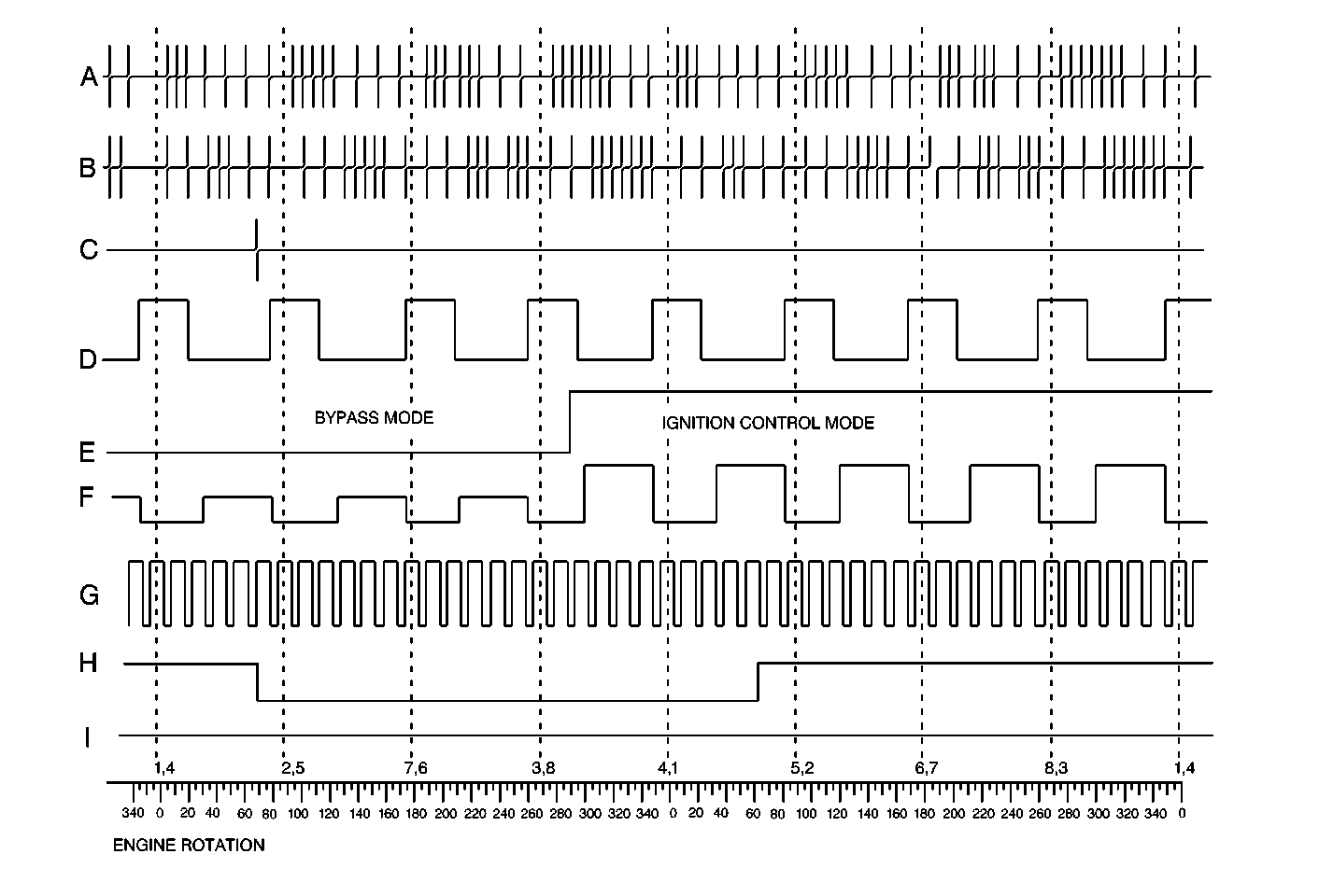
| • | It creates a 4X and 24X reference signal (4X REF HI and 24X Crank)
sent to the PCM for ignition control. |
| • | It creates a camshaft reference signal (CAM HI) sent to the PCM
for fuel injection control. |
| • | It provides a ground reference (REF LO, CAM LO) to the PCM. |
| • | It provides a means for the PCM to control spark advance (BYPASS
and IGNITION CONTROL) called IGNITION CONTROL MODE. |
| • | It provides a limited means of controlling spark advance without
PCM input called MODULE MODE. |
| • | The IC module is not repairable. When a module is replaced the
remaining components must be transferred to the new module. |
Ignition Coils
Four separate coils are mounted to the module assembly. Each coil provides
the spark for two spark plugs simultaneously (wasted spark ignition). Each
coil can be replaced separately.
Spark Plug Wires
The spark plug wires connect the ignition control module to the spark
plugs. It incorporates several plastic channels and conduits to keep it properly
positioned and to protect it. The spark plug wires are 7 mm in diameter and
the outer jacket is made of silicone to withstand high temperatures. The
silicone jacket is also an excellent insulator for the high voltages used
in the ignition system. The silicone spark plug boots provide a tight seal
on the spark plug. Care should be exercised when connecting a timing light
or other equipment. Do not force anything between the boot and wiring or
through the silicone jacket. Connections should be made using an appropriate
adapter.
Spark Plugs
Eight spark plugs are centrally located in each cylinder combustion
chamber and can be accessed through holes at the top of both cylinder bank
camshaft covers. The spark plugs have platinum pads welded to the electrodes.
These pads extend the spark plug life to 160,000 kilometers (100,000 miles).
Worn, cracked or dirty plugs may give satisfactory operation at idling
speed, but under operating conditions they frequently fail. Faulty plugs are
indicated in a number of ways: poor fuel economy, power loss, loss of speed,
hesitation, shudder, medium throttle intake manifold backfire, hard starting
and general poor engine performance.
Fouled plugs may be indicated by black carbon deposits. The black deposits
are usually the result of slow-speed driving and short runs where sufficient
engine operating temperature is seldom reached. Worn pistons, rings, faulty
ignition, over-rich fuel mixture or low heat range spark plugs may
result in carbon deposits.
Excessive gap wear on plugs of low mileage, usually indicates the engine
is operating at high speeds or loads that are consistently greater than normal
or that a plug which is too hot of a heat range is being used. Electrode
wear may also be the result of plug overheating, caused by combustion gases
leaking past the threads, due to insufficient torque of the spark plug. Excessively
lean fuel mixture will also result in excessive electrode wear.
Broken insulators are usually the result of improper installation or
carelessness when gapping the plug. Broken upper insulators usually result
from a poor fitting wrench or an outside blow. The cracked insulator may
not show up right away, but will as soon as oil or moisture penetrates the
crack. The crack is usually just below the crimped part of shell and may
not be visible.
Broken lower insulators usually result from carelessness when gapping
and generally are visible. This type of break may result from the plug operating
too Hot, which may happen in periods of high-speed operation or under heavy
loads. When gapping a spark plug, always make the gap adjustment by bending
the ground (side) electrode. Spark plugs with broken insulators should always
be replaced.
Each spark plug boot covers the spark plug terminal and a portion of
the plug insulator. These boots prevent flash-over which causes engine misfiring.
Do not mistake corona discharge for flash-over or a shorted insulator. Corona
is a steady blue light appearing around the insulator, just above the shell
crimp. It is the visible evidence of high-tension field and has no effect
on ignition performance. Usually it can be dust particles leaving a clear
ring on the insulator just above the shell. This ring is sometimes mistakenly
regarded as evidence that combustion gases have blown out between shell and
insulator.
Base Ignition Timing
The base ignition timing is determined by the relationship of the crankshaft
position sensors to the reluctor ring. This relationship is not adjustable
and results in a base ignition timing of 10° BTDC.
IC Module Mode
There are two modes of ignition system operation: PCM mode and Ignition
Control Module (IC Module) mode. In IC Module mode, the ignition system operates
independently from the PCM. The ignition control module maintains a base
ignition timing of 10° BTDC and is able to change this ignition timing
slightly with increased engine speed. IC Module mode is in effect whenever
an ignition control fault is detected while the engine is running and it
will have a noticeable effect on driveability. In PCM mode, the PCM controls
the ignition timing. The PCM calculates the desired ignition timing based
on information it receives from the input sensors.
PCM Timing Mode
The Powertrain Control Module (PCM) controls spark advance and fuel
injection for all driving conditions. The PCM monitors input signals from
the following components as part of its ignition control function to determine
the required ignition timing:
| • | Ignition Control Module (IC Module). |
| • | Engine Coolant Temperature (ECT) sensor. |
| • | Manifold Absolute Pressure (MAP) sensor. |
| • | Transaxle Range (TR) switch. |
| • | Throttle Position (TP) sensor. |
| • | Vehicle Speed Sensor (VSS). |

| • | The crankshaft reluctor ring has 24 evenly spaced notches
plus 8 additional notches (shaded) used for synchronization. |
| • | As the crankshaft rotates, the notches pass the position sensors
and create a voltage pulse signal in the sensor that is an input for the ignition
control module (ICM). |
| • | Because of the physical location of the 2 crankshaft position
sensors, the signal of B lags the signal of A by 27 degrees of crankshaft
revolution. |
| • | To synchronize the ignition, the ICM first counts the number of
B pulses between every 2 A pulses. There can be 0, 1, or 2 B
pulses between A pulses. |
| • | When the ICM sees 0 B pulses between A pulses , it starts counting
B pulses between A pulses. When the ICM counts exactly 4, it synchronizes
the ignition on the very next A pulse. If the ICM counts over 4 (jumps
from 3 to 5), it waits for another B pulse between A pulse to start counting
again. |
| • | This process allows the ignition to synchronize and fire the first
spark plug within 180 degrees (1/2 engine revolution). |
| • | The camshaft position (CMP) sensor provides the ICM with cylinder
#1 firing order information, which the PCM uses for sequential fuel injection. |
| • | Using 3 sensors allows the ICM to maintain
ignition synchronization even if one of the 3 sensors fails. |
Ignition Control Module Inputs and Outputs


