Tools Required
J 34730 Fuel Pressure Gauge
Removal Procedure
Caution: In order to Reduce the Risk of Personal Injury: Always allow for proper ventilation when working with fuel in enclosed areas.
Caution: Always wear safety goggles when working with fuel in order to protect the eyes from fuel splash.
- Relieve the fuel system fuel pressure. Refer to the Fuel Pressure Relief .
- Drain the fuel tank to at least 3/4 of a tank full. Refer to Fuel Tank Draining .
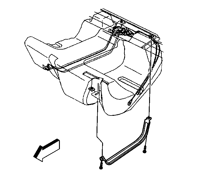
- Remove the fuel tank. Refer to Fuel Tank Replacement .
- Remove the electrical connectors at the modular fuel sender.
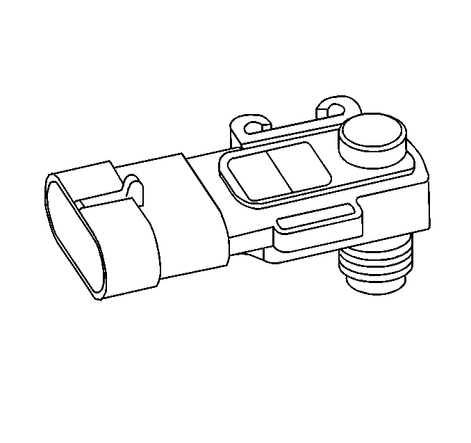
- Remove the electrical connector at the fuel tank pressure sensor.
- Remove the clip from the fuel tank pressure sensor.
- Remove the fuel tank pressure sensor (1) from the modular fuel sender.
- Clean the fuel sender assembly O-ring sealing surfaces.


Installation Procedure
- Install the fuel tank pressure sensor into the modular fuel sender.
- Install the clip to the fuel tank pressure sensor.
- Install the electrical connector at the fuel tank pressure sensor.
- Install the modular fuel sender electrical connector at the fuel tank.
- Install the fuel tank, with the aid of an assistant. Refer to Fuel Tank Replacement .
- Add fuel to the fuel tank.
- Install the fuel tank filler pipe cap (1).
- Install the negative battery cable.
- Inspect for leaks.
- Install the intake manifold top cover.


| 9.1. | Turn the ignition switch to the On position for 2 seconds. |
| 9.2. | Turn the ignition switch to the Off for 10 seconds. |
| 9.3. | Turn the ignition switch to the On position. |
| 9.4. | Check for fuel leaks. |

Notice: Use the correct fastener in the correct location. Replacement fasteners must be the correct part number for that application. Fasteners requiring replacement or fasteners requiring the use of thread locking compound or sealant are identified in the service procedure. Do not use paints, lubricants, or corrosion inhibitors on fasteners or fastener joint surfaces unless specified. These coatings affect fastener torque and joint clamping force and may damage the fastener. Use the correct tightening sequence and specifications when installing fasteners in order to avoid damage to parts and systems.
Tighten
Tighten the nuts to 3 N·m (27 lb in).
