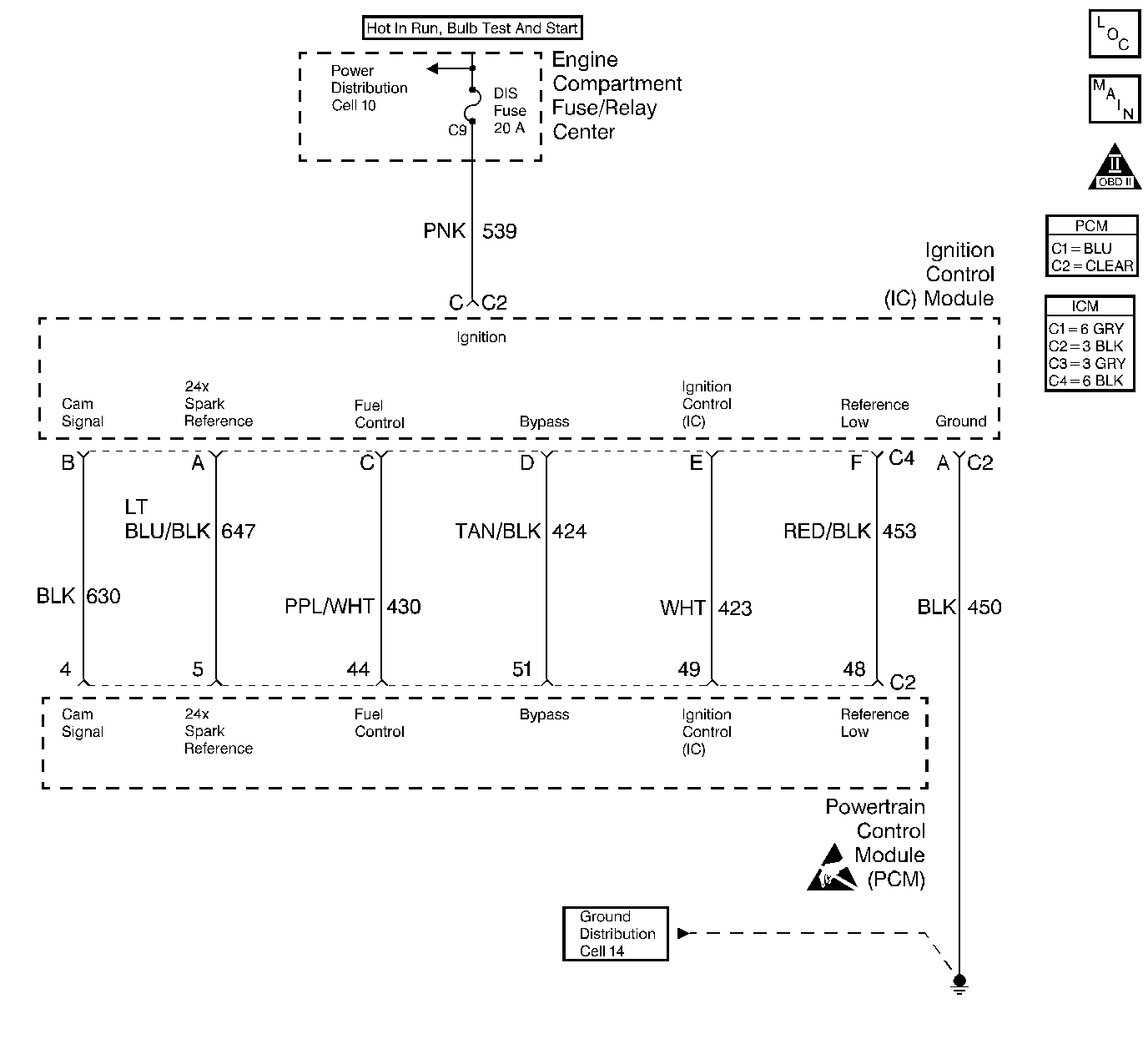
Circuit Description
The PCM applies 2.5 volts on the Ref Lo voltage (CKT 453) circuit to the Ignition Control Module. Ref Lo voltage to the PCM represents the voltage difference between Ref Lo and the PCM power ground. This is needed to ensure that the PCM and IC module signals all have the same ground reference. If the Ref Lo input voltage goes too high or low, DTC P1376 will set.
Conditions for Running the DTC
DTC P0560 is not set.
Conditions for Setting the DTC
| • | Ignition Control Module Ref Lo input is +1.48 volts or greater for 1 second. |
| OR |
| • | Ignition Control Module Ref Lo input is -1.01 volts or less for 1 second. |
Action Taken When the DTC Sets
| • | The Malfunction Indicator Lamp (MIL) will not illuminate. |
| • | No message will be displayed. |
Conditions for Clearing the DTC
| • | A History DTC will clear after forty consecutive warm-up cycles with no failures of any non-emission related diagnostic test. |
| • | A Last Test Failed (current) DTC will clear when the diagnostic runs and does not fail. |
| • | Use a scan tool to clear DTCs. |
| • | Interrupting PCM battery voltage may or may not clear DTCs. This practice is not recommended. Refer to Clearing Diagnostic Trouble Codes in PCM Description and Operation. |
Diagnostic Aids
This DTC may set due to an improperly installed PCM. This may cause the PCM to not be electrically isolated from the body ground.
Using the scan tool the normal average Ref Lo voltage displayed is 0.00 volts + or - 0.20 volts.
Test Description
Number(s) below refer to the step number(s) on the Diagnostic Table.
-
If the snapshot ignition ground voltage is 1.1 volt or less, this means that the PCM ground voltage is floating high causing P1376 to set.
-
Voltage measured at ignition control module connector C4 terminal F should be less than 0.1 volt. If the voltage is higher, then the module must have a bad ground causing the module to try to ground through the Ref Lo input to the PCM.
Step | Action | Value(s) | Yes | No |
|---|---|---|---|---|
1 | Did you perform the Powertrain On-Board Diagnostic (OBD) System Check? | -- | ||
Was the Ref Volts Low voltage the same or more than the value specified? | 1.4 volts | |||
3 |
Is the voltage more than the value specified? | 0.1 volts | ||
4 | Measure the resistance between IC module connector C4 terminal F and PCM connector C2 terminal 48. Is the resistance the same or more than the value specified? | 5 ohms | ||
With key ON, measure the voltage to ground at IC module connector C4 pin F (module side). Is the voltage the same or more than the value specified? | 0.1 volts | Go to Diagnostic Aids | ||
6 |
Is the resistance the same or more than the value specified? | 5 ohms | ||
7 |
Does this DTC reset? | -- | ||
8 |
Is the resistance at any terminal more than the value specified? | 5 ohms | ||
9 | Repair the short to voltage on the Reference Low circuit. Is the repair complete? | -- | -- | |
10 | Repair the open in the Reference Low circuit. Is the repair complete? | -- | -- | |
11 | Repair the open in the GND circuit to the IC module. Is the repair complete? | -- | -- | |
12 | Repair the open in the CKT(s) that had high resistance. Is the repair complete? | -- | -- | |
13 | Replace the Ignition Control Module. Refer to Ignition Control Module Replacement . Is the replacement complete? | -- | -- |
