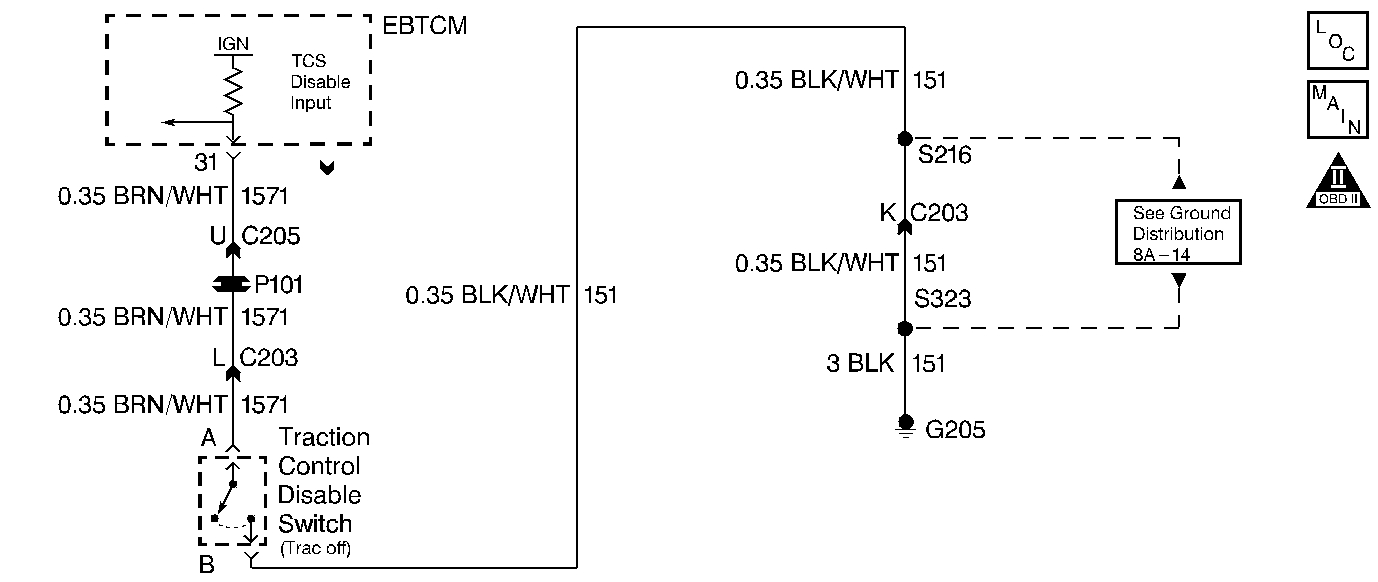
Circuit Description
The Traction Control (TRAC) OFF switch is in the glove box. This switch allows the driver to select a second gear start. Select a second gear start if the vehicle is stuck in snow, in sand, or on ice.
The TRAC OFF switch is a momentary contact switch. Depressing the switch creates a ground path for the Electronic Brake and Traction Control Module (EBTCM) ignition voltage input. When the EBTCM senses this voltage drop, the module turns OFF the traction control. The EBTCM sends a serial data message to the Platform Zone Module (PZM). The PZM sends a serial data message to the PCM. Upon receiving this signal the PCM commands a second gear start for that ignition cycle.
Following this (and every) ignition cycle, Traction Control returns to an active state. The transmission again achieves a first gear start.
The Driver Information Center (DIC) Information button is on the instrument panel. Pressing the Information button displays the Traction Control state. When the DIC displays TRACTION READY, the vehicle achieves a first gear start. When the DIC displays TRACTION OFF, the vehicle achieves a second gear start. The DIC will not update the traction status display when the TRAC OFF switch is pushed and a scan tool is installed. After removing the scan tool the ignition must be cycled in order to update the DIC.
Diagnostic Aids
| • | If, in TRACTION OFF mode, the vehicle does not achieve a second gear start, perform the following procedure: |
| - | Select 1st Gear Start on the scan tool. |
| - | Observe the current gear status on the data list. |
| - | Press the TRAC OFF switch once. Observe the display. The scan tool should indicate 1 or 2, depending on the last switch input. |
| • | When diagnosing for an intermittent short or open condition, massage the wiring harness while watching the test equipment for a change. |
Test Description
-
This Step tests for Brake System and Traction Control System DTCs. If an ABS/TCS DTC is set, repair that condition before proceeding.
-
This Step tests the function of the switch. If the scan tool display verifies the switch operation, then the fault may be intermittent.
-
This Step isolates the switch from the circuit, in order to verify that the power and ground circuits are working properly. If the displayed status changes, then the circuitry and the PCM are working properly. Removing the glove box allows access to the 2-way connector on the switch.
-
This Step verifies that the power feed circuit from the PCM to the switch is working properly.
-
This Step replaces the TRAC OFF switch. Previous Steps found no fault in the power or ground circuits. Refer to Section 8.
-
This Step refers you to Section 8. The trouble may be within the UART or Class II communication circuits.
-
This Step road tests the vehicle in both TRACTION OFF and TRACTION READY modes. Monitor the Current Gear display. A difference in acceleration verifies the repair.
Step | Action | Value(s) | Yes | No |
|---|---|---|---|---|
Are any ABS or TCS DTCs displayed? | -- | Go to Section 5 | ||
Does the Current Gear display indicate either 1 or 2 when the switch is pressed? | -- | Go to Diagnostic Aids | ||
Does the Current Gear display change? | -- | |||
Connect a fused jumper from terminal A to a known good ground. Does the Current Gear display change? | -- | |||
5 | Inspect circuit 1571 (BRN/WHT wire) for an open, a short to power, or short to ground. Refer to Electrical Diagnosis, Section 8. Did you find and correct the condition? | -- | ||
6 | Inspect circuit 151 (BLK/WHT wire) for an open or short to ground. Refer to Electrical Diagnosis, Section 8. Did you find and correct the condition? | -- | ||
Replace the TRAC OFF switch. Refer to Traction Off Switch Replacement, Section 8. Is the replacement complete? | -- | -- | ||
Refer to Body Control Module (PZM) Diagnostic System Check, Section 8. Did you find and correct a condition? | -- | -- | ||
In order to verify your repair, perform the following procedure:
Is there a difference in acceleration and performance between the two modes? | -- | System OK |
