MAP HOSE WATER/ICE ACCUMULATION CONDITION

The following information replaces the information contained in Serviceman Bulletin No. T-81-35 concerning the accumulation of water or ice in the MAP hose on 1981 DFI-equipped vehicles. Bulletin T-81-35 no longer applies and should be destroyed.
A condition of poor performance or improper cylinder mode shifts, particularly in cold weather may be caused by water or ice obstructing the Manifold Absolute Pressure (MAP) sensor hose of 1981 cars equipped with DFI engines. This may be accompanied by a "check engine" light and any or all of the diagnostic codes 31, 33, and 34. When these conditions exist, proceed as follows:
1. Gain access to MAP and BARO sensor location under dash.
2. Disconnect hose from MAP sensor and inspect for presence of water or ice in hose and/or sensor.
3. If water or ice is observed, obtain service kit P/N 1626213. This kit is required to relocate the MAP sensor under the hood to prevent water or ice accumulation in hose. This kit contains the following parts:
- MAP Sensor Jumper Harness - MAP Sensor Connector Insert - MAP Sensor Mounting Screws (Two 50mm screws required for "C" and "D" cars, and two 40mm screws required for "E" and "K" cars are included)
4. Examine MAP and BARO sensors installed in vehicle.
a. If the vehicle is equipped with Bendix MAP and BARO sensors (identified by cylindrical metal case), both should be replaced with Delco sensors. Mount only the BARO sensor inside the car using the appropriate Delco sensor mounting kit. Part numbers are as follows:
Delco MAP Sensor 16006832 Delco BARO Sensor 16006833 "C" Car Delco Sensor Mounting Kit 1623162 "E/K" Car Delco Sensor Mounting Kit 1623133
b. If the vehicle is equipped with Delco MAP and BARO sensors (identified by rectangular black plastic case), they should not be replaced. Leave the BARO sensor mounted inside the car and remove the MAP sensor and shake vigorously to remove any water that might be in the sensor. It is not necessary to replace or flush with alcohol any Delco sensor which has had water inside it.
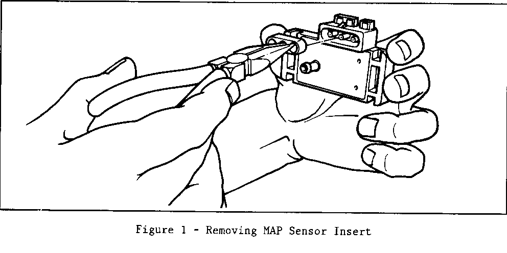
5. Remove and discard connector insert from Delco MAP sensor by carefully pulling it with needle-nose pliers, taking care not to damage sensor housing or electrical terminals (refer to Figure 1). Install new connector insert, provided in service kit, replacing previously removed insert.
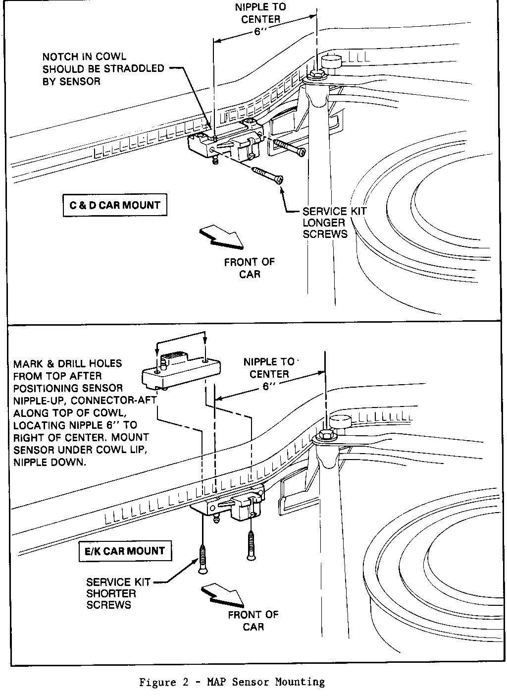
6. Position Delco MAP sensor on cowl lip in engine compartment with nipple-down, connector forward orientation (refer to Figure 2 for specific "C", "D", and "E/K" car mounting locations). MAP sensor nipple should be positioned 152mm (6 in.) to right of center. Mark and drill two 1/8 inch mounting holes. For "E/K" cars, it will be necessary to mark and drill holes from top of cowl, after positioning MAP sensor nipple-up, connector-aft along top of cowl so that nipple is located 152mm (6 inches) from center. Temporarily removing rubber filler on cowl lip will facilitate marking and drilling holes. "C" and "D" car sensor mounts require the longer (hex washer head, cross recess, self-tapping 4.2 x 1.41 x 50.0mm) screws, while "E" and "K" cars require the shorter (oval trim head, cross recess, self-tapping 4.2 x 1.41 x 40.0mm) screws contained in the service kit.
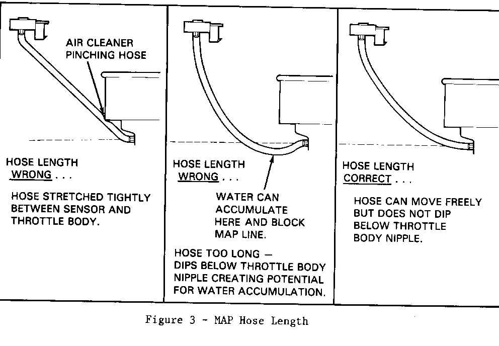
7. Pull old MAP line out through cowl grommet, disconnect line from throttle body, remove hose clamps and discard line. Cut 1/4 inch I.D. GM 6165 hose to length indicated below. This hose may be purchased in bulk (24 ft.) from GMWDD - part number 9438257. Route hose under brace from throttle body to new MAP sensor location. MAP hose length should permit some freedom of movement between MAP sensor and throttle body with air cleaner in place. Hose must not be stretched yet must be short enough to prevent dropping below throttle body level (refer to Figure 3). Trim excess hose if such sagging is observed. Fasten MAP hose to throttle body and sensor with hose clamps removed from old MAP line. Use GM 9770783 hose clamps if new clamps are required.
"C" and "D" car hose length 425mm (16.7 in.) "E/K" car hose length 525mm (20.7 in.)
8. Insert I.P. harness connector end of MAP sensor jumper harness, contained in the service kit, through the cowl opening previously used for MAP sensor hose. It may be necessary to cut grommet to accommodate connector passage. (Route harness below heater hose, pushing any excess through grommet.)
9. Connect jumper harness connectors at both MAP sensor and I.P. harness and seal cowl opening with sealer (3M08648 or equivalent).
For warranty purposes, use Operation No. T6042, MAP Sensor Relocation, at .9 hour.


General Motors bulletins are intended for use by professional technicians, not a "do-it-yourselfer". They are written to inform those technicians of conditions that may occur on some vehicles, or to provide information that could assist in the proper service of a vehicle. Properly trained technicians have the equipment, tools, safety instructions and know-how to do a job properly and safely. If a condition is described, do not assume that the bulletin applies to your vehicle, or that your vehicle will have that condition. See a General Motors dealer servicing your brand of General Motors vehicle for information on whether your vehicle may benefit from the information.
