Removal Procedure
Tools Required
| • | J 36660-A Torque/Angle Meter |
| • | J 42066 Rear Hub Holding Tool |
| • | J 42094-1 Holding Fixture |
| • | J 42094-2 Spacer |
| • | J 42094-3 Threaded Driver |
| • | J 42094-4 Threaded Arbor |
| • | J 42094-5 Ball Head |
| • | J 42094-6 Bearing Remover |
| • | J 42094-7 Threaded Spacer Pins |
| • | J 42094-8 Bearing Installer |
| • | J 42094-9 Hub Installer |
| • | J 42094-10 Thrust Bearing |
| • | J 42072 Triple Hex Head (10 mm) Deep Well Socket |
| • | J 42094-11 Spacer |
| • | J 23444-A Extreme Press Lubricant ¼ Ounce Tube |
- Raise and support the vehicle. Refer to Lifting and Jacking the Vehicle in General Information.
- Remove the tire and wheel. Refer to Tire and Wheel Removal and Installation in Tires and Wheels.
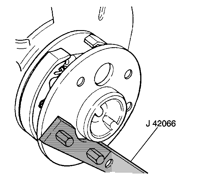
- Use the J 42066 and use a ½ in breaker bar to counter hold the rear wheel hub.
- Remove the wheel drive shaft bolts (1).
- Remove the wheel drive shaft from the rear wheel hub flange.
- Remove the rear brake caliper. Refer to Rear Brake Caliper Replacement in Disc Brakes.
- Suspend the rear brake caliper.
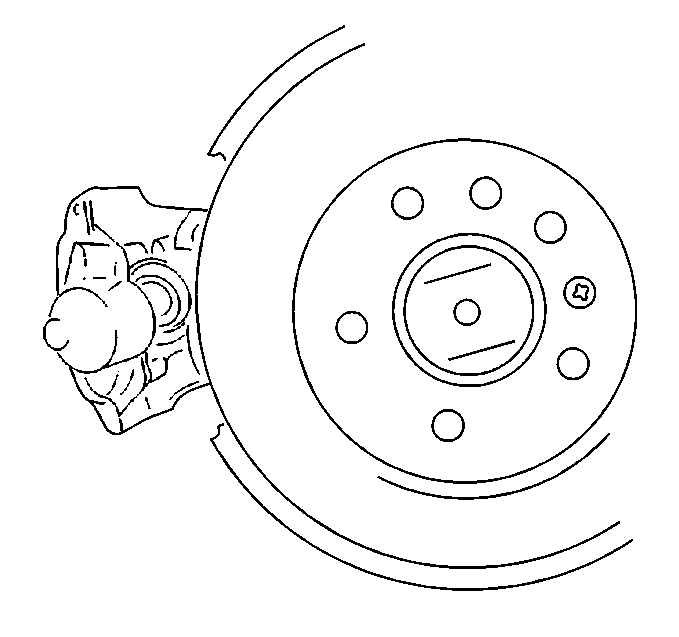
- Remove the brake disc rotor set screw.
- Remove the brake disc rotor. It may be necessary to back off the parking brake adjustment to remove the brake disc rotor. Refer to Park Brake Adjustment in Parking Brake.
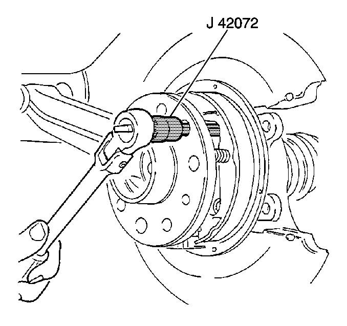
- Use the J 42072 to back out 3 of the 4 brake backing plate bolts to approximately 9 revolutions or about 12 mm (0.47 in). This will allow for the rear wheel hub puller pin installation.
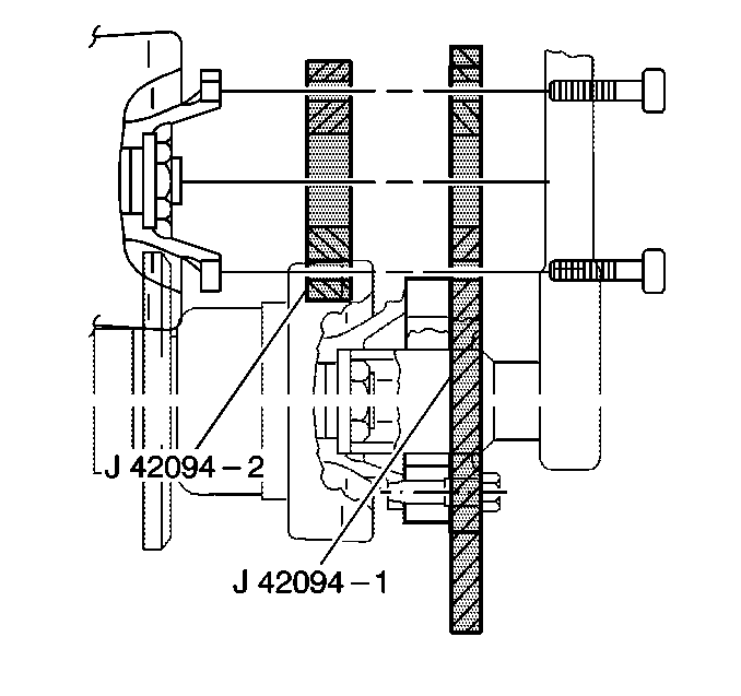
- Attach the J 42094-2 and attach the J 42094-1 to the rear wheel hub flange to hold the rear wheel hub while removing the rear wheel hub nut. Use the drive shaft bolts if necessary.
- Remove the rear wheel hub nut.
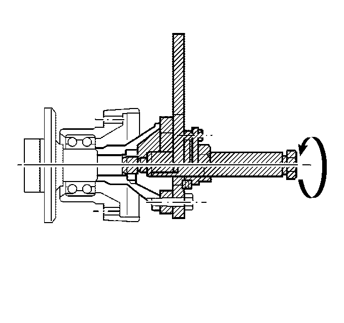
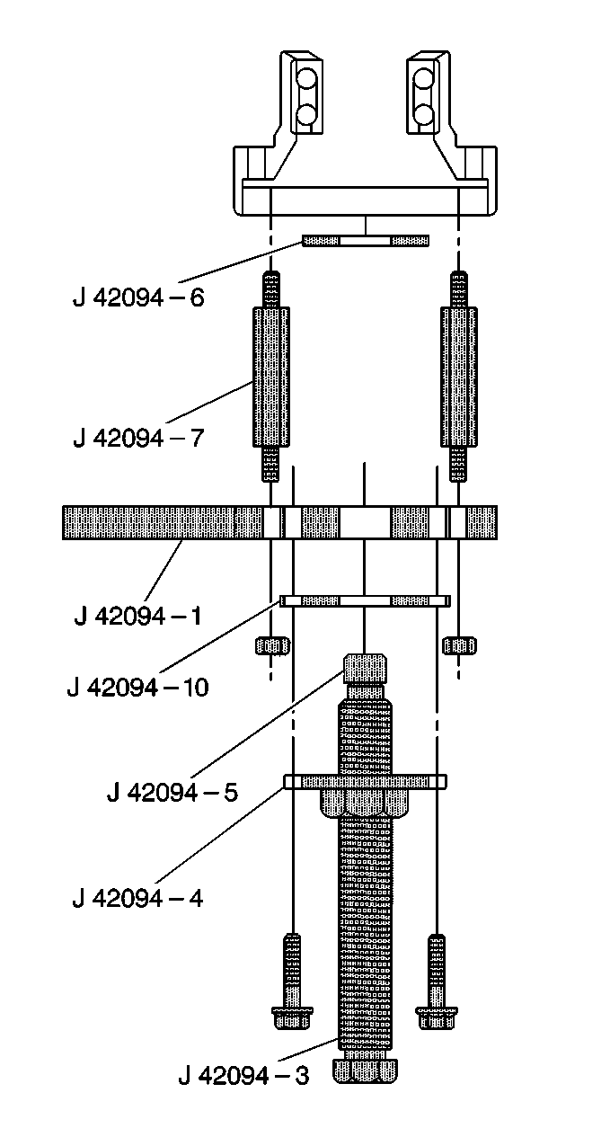
- Lubricate the threads of the J 42094-3 withJ 23444-A .
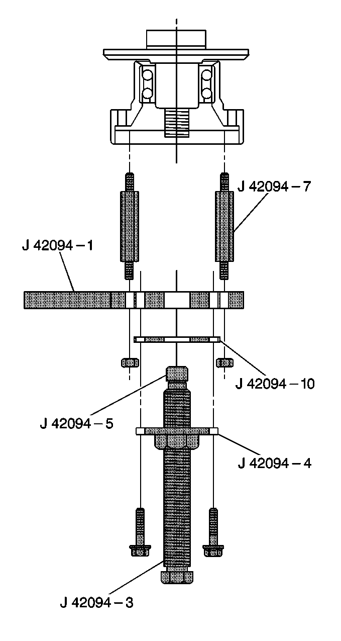
- Place the J 42094-5 onto the J 42094-3 .
- Use the J 42094-10 as a spacer to attach the J 42094-4 to the J 42094-1 with the supplied 3 bolts.
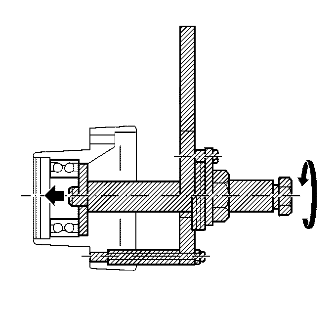
- Turn the J 42094-3 clockwise to pull off the rear wheel hub flange.
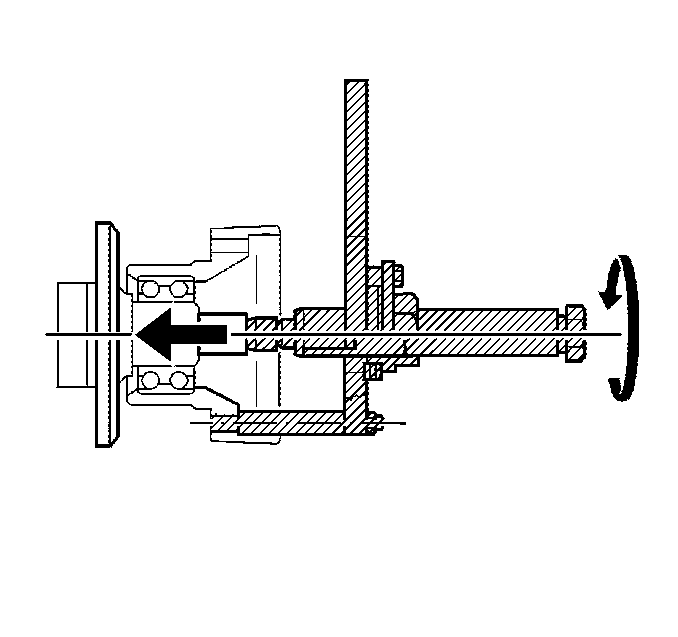
- Screw the J 42094-7 into the rear knuckle.
- Attach the J 42094-1 with the stem pointed upward, to the J 42094-7 .
- Turn the J 42094-3 clockwise to press out the rear wheel hub.
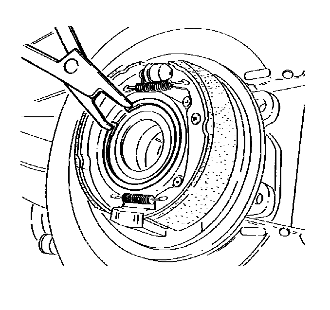
- Remove the wheel bearing retaining ring.
- Attach the J 42094-6 to the end of the threaded driver.
- Turn the J 42094-3 clockwise to press out the bearing.
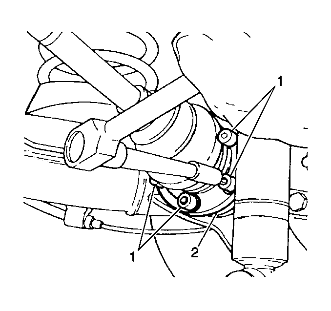
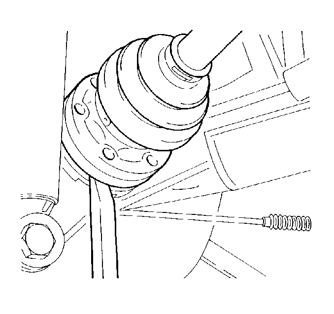
Important: DO NOT allow the drive shaft to hang freely. Suspend the wheel drive shaft upward.
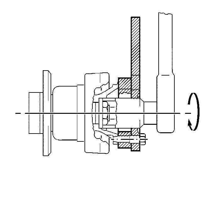
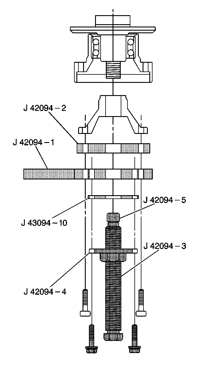
Attach the J 42094-3 into the J 42094-4 .
Installation Procedure
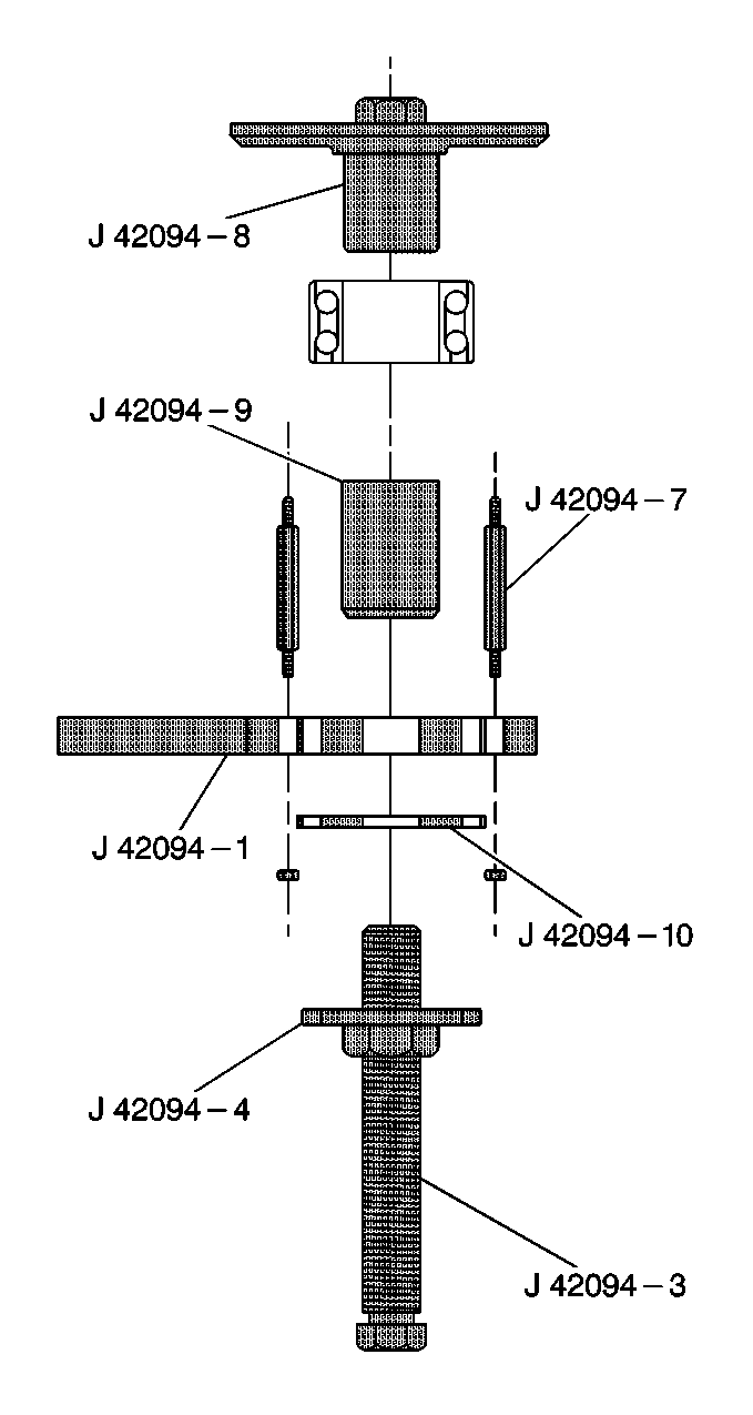
- Insert the J 42094-8 through the wheel bearing.
- Install the J 42094-9 and J 42094-11 onto the shaft of the J 42094-3 .
- Thread theJ 42094-8 into the J 42094-3 .
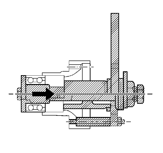
- Turn the J 42094-4 while holdingJ 42094-3 to press the wheel bearing in until fully seated.
- Remove the J 42094-8 from the tool setup.
- Install the wheel bearing retaining ring.
- Attach the J 42094-1 to the J 42094-7 .
- Remove the supplied anchoring bolts from the J 42094-4 .
- Thread the rear wheel hub into the J 42094-3 .
- Draw the rear wheel hub into the wheel bearing by holding the J 42094-3 and turning theJ 42094-4 clockwise.
- Remove the tool assembly from the vehicle.
- Use wheel drive shaft bolts to connect the following special tools to the rear wheel flange:
- Install the rear wheel hub flange to the rear wheel hub. Ensure the splines are aligned properly.
- Press the rear wheel hub flange fully onto the rear wheel hub by turning the J 42094-4 clockwise and counter-holding with the J 42094-3 .
- Remove the following special tools:
- Leave the following special tools attached to the rear wheel flange:
- Install the rear wheel hub nut.
- Remove the following special tools after tightening the rear wheel hub nut:
- Install the retaining washer.
- Install the brake backing plate bolts.
- Install the brake disc rotor.
- Install the brake disc rotor set screw.
- Install the rear brake caliper. Refer to Rear Brake Caliper Replacement in Disc Brakes.
- Install the wheel drive shaft to the rear wheel hub flange.
- Use the J 42066 to counter hold the rear wheel hub.
- Install the wheel drive shaft bolts (1).
- Install the tire and wheel. Refer to Tire and Wheel Removal and Installation in Tires and Wheels.
- Lower the vehicle.

Important:
• Center the J 42094-3
inside of the wheel bearing to prevent binding of the rear wheel hub
while drawing it into the bearing. • Adjust the J 42094-7
if necessary.
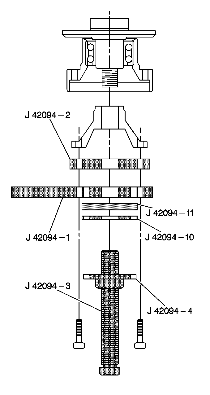
| • | Connect theJ 42094-4 . |
| • | Connect theJ 42094-3 . |
| • | Connect theJ 42094-1 . |
| • | Connect theJ 42094-2 . |
| • | Connect theJ 42094-11 . |
| • | Connect theJ 42094-10 . |
| • | Remove the J 42094-4 . |
| • | Remove the J 42094-3 . |
| • | Remove the J 42094-10 . |
| • | Remove the J 42094-11 . |

| • | Leave the J 42094-1 . |
| • | Leave the J 42094-2 . |
Notice: Use the correct fastener in the correct location. Replacement fasteners must be the correct part number for that application. Fasteners requiring replacement or fasteners requiring the use of thread locking compound or sealant are identified in the service procedure. Do not use paints, lubricants, or corrosion inhibitors on fasteners or fastener joint surfaces unless specified. These coatings affect fastener torque and joint clamping force and may damage the fastener. Use the correct tightening sequence and specifications when installing fasteners in order to avoid damage to parts and systems.
Tighten
Tighten the rear wheel hub nut to 300 N·m (221 lb ft).
| • | Remove the J 42094-1 . |
| • | Remove the J 42094-2 . |
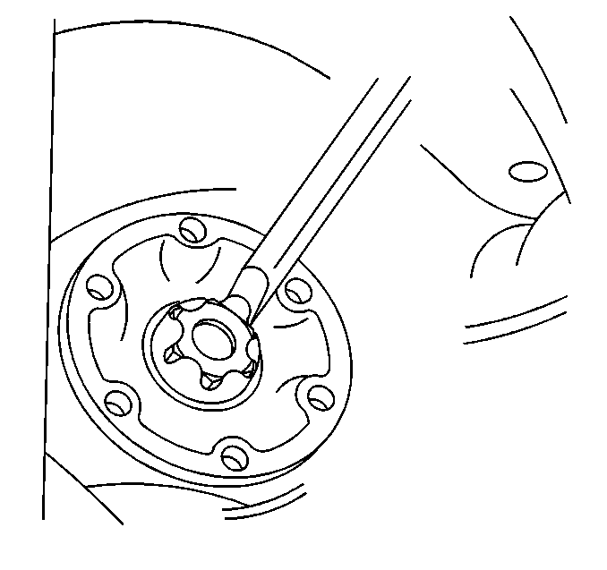
Peen the retaining washer to the rear wheel hub nut.

Tighten
Use theJ 42072
and J 36660-A
to tighten
the brake backing plate bolts to 50 N·m (37 lb ft +
40 degrees).

Tighten
Tighten the disc brake rotor screw to 4 N·m (35 lb in).


Tighten
Use J 36660-A
to
tighten the wheel drive shaft bolts (1) to 50 N·m
(37 lb ft + 70 degrees).
