| |||||||
|---|---|---|---|---|---|---|---|
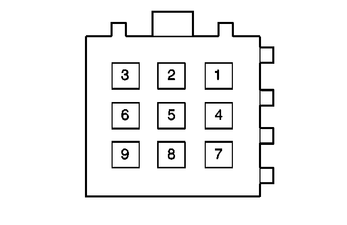
Connector Part Information |
| ||||||
Pin | Wire Color | Circuit No. | Function | ||||
1 | BRN | X410 | B+ from Fuse #14 | ||||
2 | BLK | F410 | Ground to G201 | ||||
3 | BRN/WHT | XM161 | Serial Data Class 2 | ||||
4 | RED | A411 | B+ from Multifunction Relay K134 | ||||
5 | WHT | M16 | Cell Phone Negative Output | ||||
6 | BRN/WHT | XM16 | Cell Phone Positive Output | ||||
7-9 | -- | -- | Not Used | ||||

| |||||||
|---|---|---|---|---|---|---|---|
Connector Part Information |
| ||||||
Pin | Wire Color | Circuit No. | Function | ||||
1 | BRN | X10 | B+ from Fues #14 | ||||
2 | BLK | F10 | Ground to G201 | ||||
3 | BRN/WHT | XM15 | Serial Data Class 2 | ||||
4 | RED | A11 | B+ from Mulotifunction Relay K134 | ||||
5 | WHT | M16 | Cell Phone Negative Output | ||||
6 | BRN/WHT | XM16 | Cell Phone Positive Output | ||||
7-9 | -- | -- | Not Used | ||||

| |||||||
|---|---|---|---|---|---|---|---|
Connector Part Information |
| ||||||
Pin | Wire Color | Circuit No. | Function | ||||
1 | BLK | F10 | CD Common | ||||
2 | WHT | M17 | LH CD Output Signal | ||||
3 | BLU | P15 | RH CD Output Signal | ||||
4 | BLK | S2 | Shield Wire | ||||
5 | RED | A211 | B+ from Fuse #8 | ||||
6 | BLK | F111 | Ground to G201 | ||||
7 | YEL | B220 | CD Data Bus | ||||
8-9 | -- | -- | Not Used | ||||
| |||||||
|---|---|---|---|---|---|---|---|
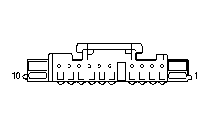
Connector Part Information |
| ||||||
Pin | Wire Color | Circuit No. | Function | ||||
1 | WHT | M45 | LH CD Output Signal | ||||
2 | BLU | P45 | RH CD Output Signal | ||||
3 | BLK | F45 | CD Common | ||||
4 | S5 | Shield Wire | |||||
5 | RED | A201 | B+ from Fuse #8 | ||||
6 | -- | -- | Not Used | ||||
7 | BLK | F101 | Ground to G201 | ||||
8-9 | -- | -- | Not Used | ||||
10 | YEL | B20 | CD Data Bus | ||||
| |||||||
|---|---|---|---|---|---|---|---|
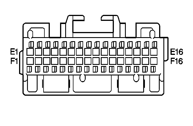
Connector Part Information |
| ||||||
Pin | Wire Color | Circuit No. | Function | ||||
E1 | YEL | B220 | CD Data Bus | ||||
E2-E4 | -- | -- | Not Used | ||||
E5 | GRY/YEL | RB40 | Illumination Signal | ||||
E6 | -- | -- | Not Used | ||||
E7 | WHT | M16 | Cellular Phone Negative Input | ||||
E8 | BRN/WHT | XM16 | Cellular Phone Positive Input | ||||
E9 | -- | -- | Not Used | ||||
E10 | BLK | F10 | CD Common | ||||
E11 | WHT | M17 | LH CD Input Signal | ||||
E12 | GRN | U41 | LH Rear Positive Output | ||||
E13 | BRN/GRN | XU42 | LH Rear Negative Output | ||||
E14 | BRN/YEL | XB10 | RH Front Negative Output | ||||
E15 | YEL | B8 | RH Front Positive Output | ||||
E16 | BLK | F40 | Ground to G201 | ||||
F1 | RED | A52 | B+ from Multifunction Relay K134 | ||||
F2 | -- | -- | Not Used | ||||
F3 | RED/WHT | AM110 | Radio ON Signal Output | ||||
RED/WHT | AM116 | Radio ON Signal Output | |||||
F4 | GRY/GRN | RU72 | B+ from Fuse #26 | ||||
F5 | BLK | F49 | Ground to G201 | ||||
F6 | BRN/WHT | XM830 | Serial Data (Class 2) | ||||
F7 | -- | -- | Not Used | ||||
F8 | BLU/RED | PA101 | Steering Wheel Switch Input | ||||
F9 | BLK | B899 | Ground to G201 | ||||
F10 | -- | -- | Not Used | ||||
F11 | BLU | P15 | RH CD Input Signal | ||||
F12 | BLU | P1 | LH Front Positive Output | ||||
F13 | BRN/BLU | XP4 | LH Front Negative Output | ||||
F14 | BRN/WHT | XM42 | RH Rear Negative Output | ||||
F15 | WHT | M42 | RH Rear Positive Output | ||||
F16 | -- | -- | Not Used | ||||
| |||||||
|---|---|---|---|---|---|---|---|
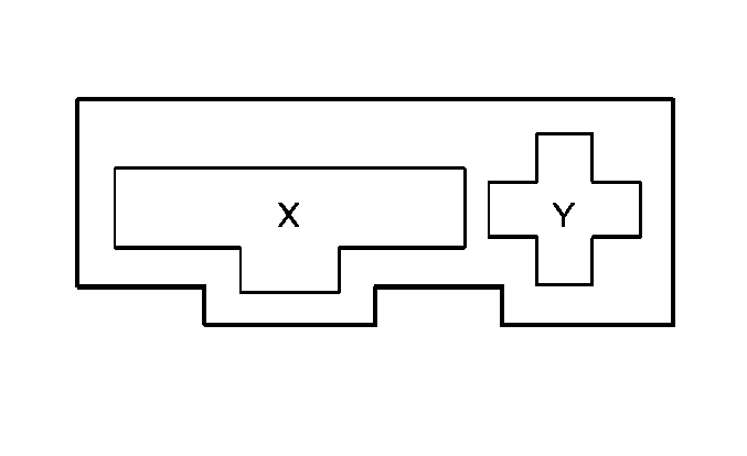
Connector Part Information |
| ||||||
Pin | Wire Color | Circuit No. | Function | ||||
X | BRN | X16 | B+ When Defogger is ON | ||||
Y | RED/WHT | AM42 | Radio ON Signal | ||||

| |||||||
|---|---|---|---|---|---|---|---|
Connector Part Information |
| ||||||
Pin | Wire Color | Circuit No. | Function | ||||
E1 | YEL | B20 | Sound Processor Signal | ||||
E2-E4 | -- | -- | Not Used | ||||
E5 | GRY/YEL | RB40 | Illumination Signal | ||||
E6-E11 | -- | -- | Not Used | ||||
E12 | WHT | M92 | LH Negative Output | ||||
E13 | WHT | XM92 | LH Positive Output | ||||
E14 | BLK | S47 | Shield Wire | ||||
E15 | BLK | S46 | Shield Wire | ||||
E16 | BLK | F40 F49 | Ground to G201 | ||||
F1 | RED | A52 | B+ from Multifunction Relay K134 | ||||
F2 | -- | -- | Not Used | ||||
F3 | RED/WHT | AM110 | Radio ON Signal | ||||
RED/WHT | AM116 | Radio ON Signal | |||||
F4 | GRY/GRN | RU72 | B+ from Fuse #26 | ||||
F5 | BLK | F49 | Ground to G201 | ||||
F6 | BRN/WHT | XM45 | Serial Data (Class 2) | ||||
F7 | -- | -- | Not Used | ||||
F8 | BLU/RED | PA101 | Remote Control Signal | ||||
F9 | BLK | F899 | Remote Control Signal | ||||
F10 | -- | -- | Not Used | ||||
F11 | BLK | S45 | Shield Wire | ||||
F12 | WHT | M90 | Chime Positive Output (Not Used) | ||||
F13 | BRN/WHT | XM93 | Chime Negative Output (Not Used) | ||||
F14 | WHT | M91 | RH Negative Output | ||||
F15 | BRN/WHT | XM91 | RH Positive Output | ||||
F16 | -- | -- | Not Used | ||||
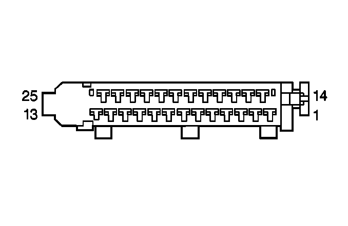
| |||||||
|---|---|---|---|---|---|---|---|
Connector Part Information |
| ||||||
Pin | Wire Color | Circuit No. | Function | ||||
1 | GRN | U3 | RH Rear Speaker Signal Output | ||||
2 | BRN/GRN | XU3 | RH Rear Speaker Signal Output | ||||
3 | BRN/BLU | XP12 | LH Front Negative Input | ||||
4 | BRN/YEL | XB12 | RH Front Negative Input | ||||
5 | BRN/GRN | XU12 | LH Rear Negative Input | ||||
6 | BRN/WHT | XM10 | RH Rear Negative Input | ||||
7 | WHT | M9 | RH Rear Positive Input | ||||
8 | GRN | U11 | LH Rear Positive Input | ||||
9 | YEL | B11 | RH Front Positive Input | ||||
10 | BLU | P11 | LH Front Positive Input | ||||
11-12 | -- | -- | Not Used | ||||
13 | RED | A202 | B+ from Fuse #6 | ||||
14 | WHT | M3 | LH Rear Speaker Signal Output | ||||
15 | BRN/WHT | XM3 | LH Rear Speaker Signal Output | ||||
16 | BRN/BLU | XP2 | LH Front Door Speaker Output | ||||
17 | BLU | P2 | LH Front Door Speaker Output | ||||
18 | YEL | B4 | RH Front Door Speaker Output | ||||
19 | BRN/YEL | XB11 | RH Front Door Speaker Output | ||||
20 | GRN | U43 | LH Rear Door Speaker Output | ||||
21 | BRN/GRN | XU43 | LH Rear Door Speaker Output | ||||
22 | WHT | M43 | RH Rear Door Speaker Output | ||||
23 | BRN/WHT | XM43 | RH Rear Door Speaker Output | ||||
24 | BLK | F90 | Ground | ||||
25 | RED | A150 | Amp Enable Input | ||||
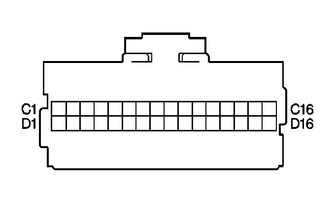
| |||||||
|---|---|---|---|---|---|---|---|
Connector Part Information |
| ||||||
Pin | Wire Color | Circuit No. | Function | ||||
C1-D1 | -- | -- | Not Used | ||||
D2 | RED | A150 | Amp Enable Output | ||||
D3-D11 | -- | -- | Not Used | ||||
D12 | BRN/WHT | XM90 | Chime Negative Input (Not Used) | ||||
D13 | WHT | M90 | Chime Positive Input (Not Used) | ||||
D14 | WHT | M16 | Cell Phone Negative Input | ||||
D15 | BRN/WHT | XM16 | Cell Phone Positive Input | ||||
D16 | -- | -- | Not Used | ||||
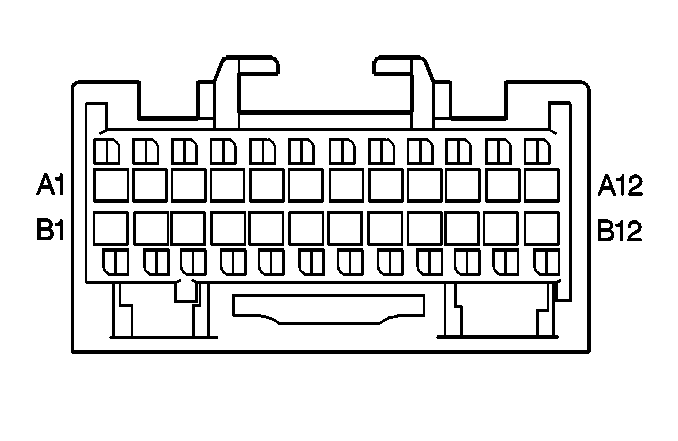
| |||||||
|---|---|---|---|---|---|---|---|
Connector Part Information |
| ||||||
Pin | Wire Color | Circuit No. | Function | ||||
A1 | BLK | F151 | Ground | ||||
A2 | BRN/WHT | XM10 | RH Rear Negative Output | ||||
A3 | WHT | M9 | RH Rear Positive Output | ||||
A4 | BLK | SO3 | Shield Wire | ||||
A5 | BRN/GRN | XU12 | LH Rear Negative Output | ||||
A6 | GRN | U11 | LH Rear Positive Output | ||||
A7 | BLK | SO4 | Shield Wire | ||||
A8 | BRN/YEL | XB12 | RH Front Negative Output | ||||
A9 | YEL | B11 | RH Front Positive Output | ||||
A10 | BLK | SO1 | Shield Wire | ||||
A11 | BRN/BLU | XP12 | LH Front Negative Output | ||||
A12 | BLU | P11 | LH Front Positive Output | ||||
B1 | RED | A205 | B+ from Multifunction Relay K134 | ||||
B2 | -- | -- | Not Used | ||||
B3 | BRN/WHT | XM45 | Serial Data (Class 2) | ||||
B4 | BRN/WHT | XM92 | LH Positive Input | ||||
B5 | WHT | M92 | LH Negative Input | ||||
B6 | WHT | M91 | RH Negative Input | ||||
B7 | BRN/WHT | XM91 | RH Positive Input | ||||
B8 | WHT | M45 | LH CD Positive Input | ||||
B9 | BLK | F45 | CD Common | ||||
B10 | -- | -- | Not Used | ||||
B11 | BLU | P45 | RH CD Positive Input | ||||
B12 | BLK | SO2 | Shield Wire | ||||
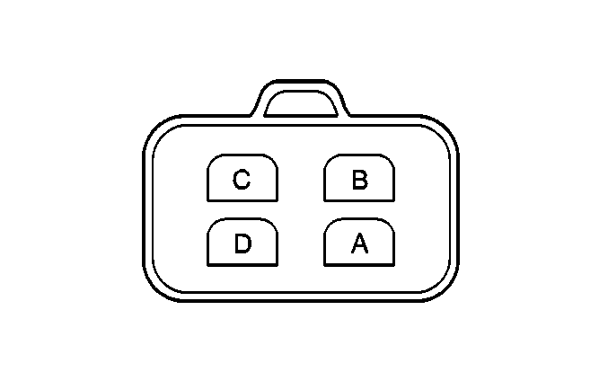
| |||||||
|---|---|---|---|---|---|---|---|
Connector Part Information |
| ||||||
Pin | Wire Color | Circuit No. | Function | ||||
A | GRY | R1 | LED Output Control | ||||
B | BLU/RED | PA101 | Steering Wheel Switch Input | ||||
C | -- | -- | Not Used | ||||
D | BRN | X1 | Ground | ||||
