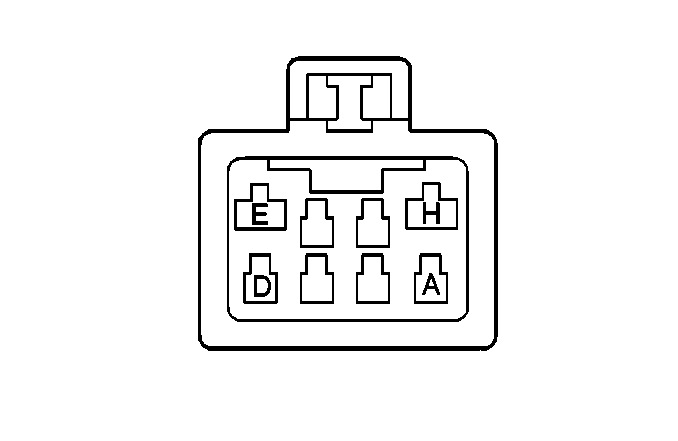
| |||||||
|---|---|---|---|---|---|---|---|
Connector Part Information |
| ||||||
Pin | Wire Color | CircuitNo. | Function | ||||
A | BLK/BLU | FP733 | Transmission Position Signal | ||||
B | BLK/GRN | FU726 | Transmission Position Signal | ||||
C | BLK/YEL | FB708 | Transmission Position Signal | ||||
D | BRN | X756 | B+ from Fuse #3 | ||||
E | BLK/RED | FA501 | Starter Solenoid Signal | ||||
F | WHT/BLK | MF757 | Rear View Mirror/Backup Lamp Supply Voltage | ||||
G | GRY | R733 | Transmission Position Signal | ||||
H | BLK/RED | FA500 | B+ in the ON Position | ||||
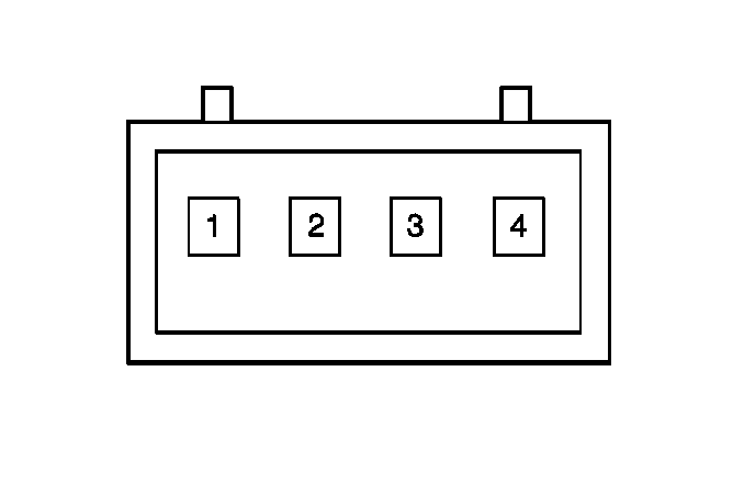
| |||||||
|---|---|---|---|---|---|---|---|
Connector Part Information |
| ||||||
Pin | Wire Color | Circuit No. | Function | ||||
1 | BRN | X812 | 5 V Reference | ||||
2 | BLK/WHT | FM60 | Sun Sensor Input Signal | ||||
3 | BLK | F830 | TS Day/Night Signal | ||||
4 | BLU | P111 | Sensor Ground | ||||
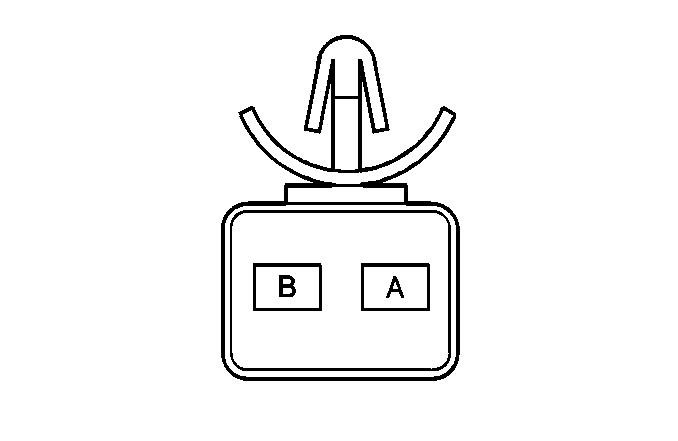
| |||||||
|---|---|---|---|---|---|---|---|
Connector Part Information |
| ||||||
Pin | Wire Color | CircuitNo. | Function | ||||
A | BLK | F3 | Ground to G400 | ||||
B | BLK/YEL | FB15 | Backup Lamp Supply Voltage | ||||
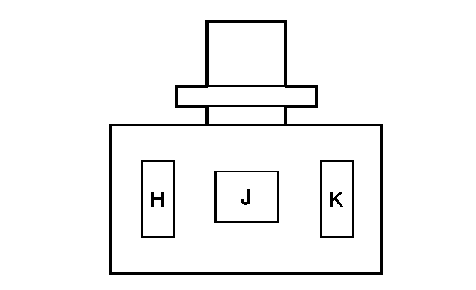
| |||||||
|---|---|---|---|---|---|---|---|
Connector Part Information |
| ||||||
Pin | Wire Color | Circuit No. | Function | ||||
H | BLK | F2 | Ground to G400 | ||||
J | GRY/GRN | RU2 | Lamp ON Signal | ||||
K | WHT/BLK | MF1 | Lamp ON Feed | ||||

| |||||||
|---|---|---|---|---|---|---|---|
Connector Part Information |
| ||||||
Pin | Wire Color | Circuit No. | Function | ||||
H | BLK | F1 | Ground to G400 | ||||
J | GRY/GRN | RU3 | Lamp ON Signal | ||||
K | WHT/BLK | MF10 | Lamp ON Feed | ||||
WHT/BLK | MF1 | Lamp ON Feed | |||||
| |||||||
|---|---|---|---|---|---|---|---|
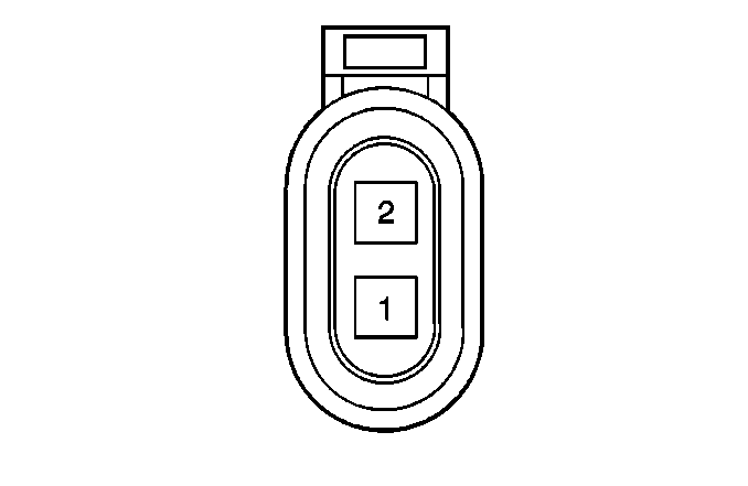
Connector Part Information |
| ||||||
Pin | Wire Color | Circuit No. | Function | ||||
1 | GRY/BLK | RF1 | Cornering Lamp Supply Voltage | ||||
2 | BLK | F2 | Ground to G103 | ||||

| |||||||
|---|---|---|---|---|---|---|---|
Connector Part Information |
| ||||||
Pin | Wire Color | Circuit No. | Function | ||||
1 | GRY/RED | RA1 | Lamp ON Signal | ||||
2 | BLK | F5 | Ground to G103 | ||||
| |||||||
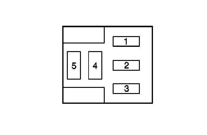
|---|---|---|---|---|---|---|---|
Connector Part Information |
| ||||||
Pin | Wire Color | Circuit No. | Function | ||||
1 | WHT | M70 | Relay Control | ||||
2 | WHT | M65 | DRL High Beam Series Circuit | ||||
3 | RED | A832 | B+ from Fuse #21 | ||||
4 | BLK | F803 | Ground to G103 | ||||
5 | BLK/WHT | FM19 | LH Headlamp Control Ground | ||||

| |||||||
|---|---|---|---|---|---|---|---|
Connector Part Information |
| ||||||
Pin | Wire Color | Circuit No. | Function | ||||
1 | BRN/BLU | XP806 | Interior Lamps Relay Output Ground | ||||
2 | BLK | F901 | Ground to G103 | ||||
3 | RED/BLU | AP882 | Courtesy Lamps Supply Voltage | ||||
4 | RED/BLU | AP808 | Courtesy Lamps Supply Voltage | ||||
| |||||||
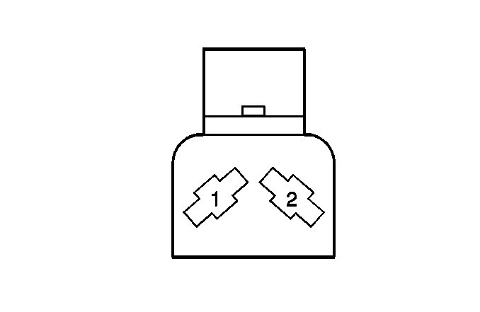
|---|---|---|---|---|---|---|---|
Connector Part Information |
| ||||||
Pin | Wire Color | Circuit No. | Function | ||||
1 | GRY/WHT | RM2 | Door Open Signal | ||||
2 | GRY | R2 | Door Jamb Signal | ||||

| |||||||
|---|---|---|---|---|---|---|---|
Connector Part Information |
| ||||||
Pin | Wire Color | Circuit No. | Function | ||||
1 | -- | -- | Not Used | ||||
2 | GRY | R6 | Door Open Signal | ||||

| |||||||
|---|---|---|---|---|---|---|---|
Connector Part Information |
| ||||||
Pin | Wire Color | Circuit No. | Function | ||||
1 | GRY | R2 | Door Open Signal | ||||
2 | GRY | R1 | Door Open Signal | ||||

| |||||||
|---|---|---|---|---|---|---|---|
Connector Part Information |
| ||||||
Pin | Wire Color | Circuit No. | Function | ||||
1 | GRY | R2 | Door Open Signal | ||||
2 | GRY | R1 | Door Jamb Signal | ||||

| |||||||
|---|---|---|---|---|---|---|---|
Connector Part Information |
| ||||||
Pin | Wire Color | CircuitNo. | Function | ||||
1 | BRN | X2 | Lamp ON Signal | ||||
2 | BLK | F3 | Ground to G103 | ||||

| |||||||
|---|---|---|---|---|---|---|---|
Connector Part Information |
| ||||||
Pin | Wire Color | Circuit No. | Function | ||||
1 | GRN | X3 | Lamp ON Signal | ||||
2 | BLK | F4 | Ground to G103 | ||||
| |||||||
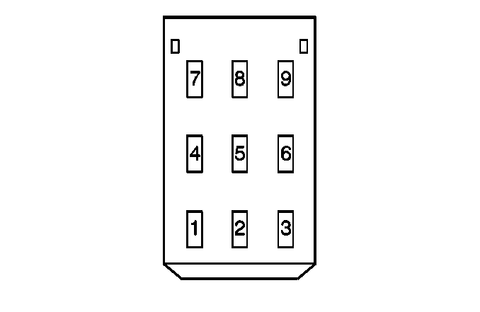
|---|---|---|---|---|---|---|---|
Connector Part Information |
| ||||||
Pin | Wire Color | Circuit No. | Function | ||||
1 | BLK/WHT | FM22 | Turn Signal Flasher Signal Circuit | ||||
2 | BLK | F27 | Ground to G103 | ||||
3 | BLU | P3 | Ignition Positive Voltage | ||||
4 | BLK/WHT | FM3 | Hazard Switch LH Signal | ||||
5 | -- | -- | Not Used | ||||
6 | RED | A9 | B+ from Fuse #12 | ||||
7 | BLK/GRN | FU3 | Hazard Switch RH Signal | ||||
8 | GRY/YEL | RB77 | Interior Lamps Dimming Control | ||||
GRY/YEL | RB70 | Interior Lamps Dimming Control | |||||
9 | BRN | X10 | B+ from Fuse #3 | ||||
| |||||||
|---|---|---|---|---|---|---|---|
Connector Part Information |
| ||||||
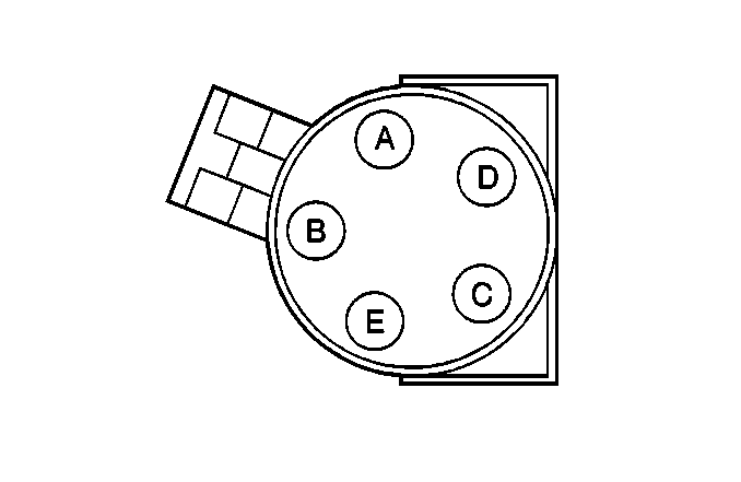
Pin | Wire Color | Circuit No. | Function | ||||
A | -- | -- | Not Used | ||||
B | BLK/WHT | FM13 | High Beam Signal | ||||
C | YEL | B1 | Low Beam Signal (w/o T97) | ||||
D | BLK | F840 | Ground to G103 | ||||
E | WHT | M2 | High Beam Signal | ||||

| |||||||
|---|---|---|---|---|---|---|---|
Connector Part Information |
| ||||||
Pin | Wire Color | Circuit No. | Function | ||||
A | -- | -- | Not Used | ||||
B | BLK | F11 | Ground to G103 | ||||
C | YEL | B3 | Low Beam Voltage (w/o T97) | ||||
D | -- | -- | Not Used | ||||
E | WHT | M1 | RH High Beam Supply Voltage | ||||
| |||||||
|---|---|---|---|---|---|---|---|
Connector Part Information |
| ||||||
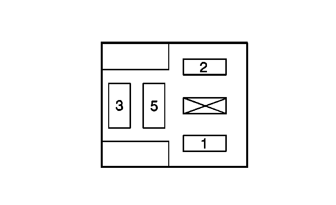
Pin | Wire Color | CircuitNo. | Function | ||||
1 | BRN/PPL | XY802 | Relay Control | ||||
2 | -- | -- | Not Used | ||||
3 | RED | A825 | B+ from Fuse #21 | ||||
4 | WHT | M8 | LH High Beam Supply Voltage | ||||
5 | RED | A10 | B+ from Fuse #21 | ||||
| |||||||
|---|---|---|---|---|---|---|---|
Connector Part Information |
| ||||||
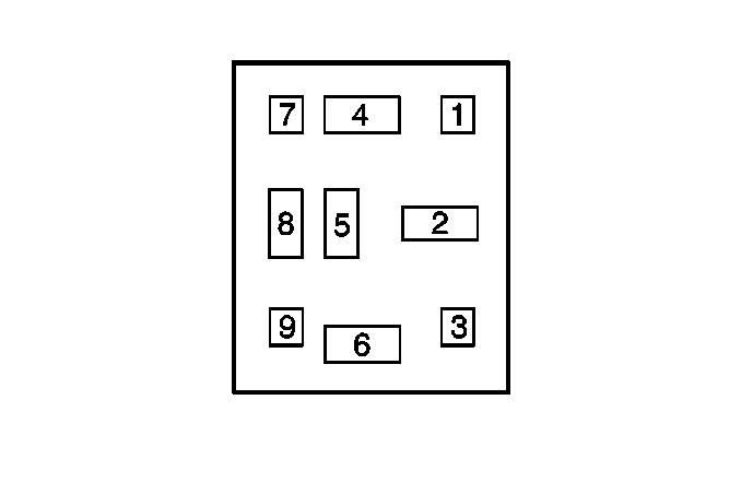
Pin | Wire Color | Circuit No. | Function | ||||
1 | -- | -- | Not Used | ||||
2 | RED | A850 | B+ from Fuse #32 | ||||
3 | -- | -- | Not Used | ||||
4 | RED | A827 | B+ from Fuse #32 | ||||
5 | BLK/RED | FA888 | Switched Battery Voltage for Fog Lamps | ||||
6 | WHT | M62 | Relay Control | ||||
7 | -- | -- | Not Used | ||||
8 | WHT | M64 | RH High Beam Supply Voltage | ||||
WHT | M65 | RH High Beam Supply Voltage | |||||
9 | -- | -- | Not Used | ||||
| |||||||
|---|---|---|---|---|---|---|---|
Connector Part Information |
| ||||||
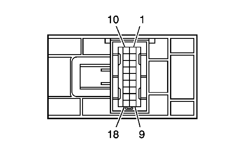
Pin | Wire Color | Circuit No. | Function | ||||
1 | GRY/GRN | RU70 | B+ from Fuse #26 | ||||
2 | GRY/YEL | RB1 | Interior Lamps Dimming Control | ||||
3 | BRN | X22 | B+ from Fuse #15 | ||||
4 | BRN/RED | XA811 | Low Beam Relay Control Signal | ||||
5 | BRN/WHT | XM815 | Park Lamp Relay Control Signal | ||||
6 | YEL | B60 | Low Beam ON/OFF Signal | ||||
7 | RED/WHT | AM813 | Park Lamp ON/OFF Signal | ||||
8 | BRN/PPL | XY112 | Interior Lamps Switch Signal | ||||
9 | RED/YEL | AB810 | TS ON/OFF Signal | ||||
10 | BLK/BLU | FP28 | Fog Lamp Switch Signal | ||||
11 | BLK/BRN | FX810 | TS Delay Signal | ||||
12 | BLK/PPL | FY810 | TS Return Signal | ||||
13 | BLK | F18 | Ground to G103 | ||||
14 | YEL | B55 | B+ form Fuse #22 | ||||
15 | -- | -- | Not Used | ||||
16 | BRN/BLK | XF830 | TS Indicator | ||||
17 | RED | A5 | B+ from Fuse #8 | ||||
18 | GRY/WHT | RM901 | Chime Control Signal | ||||
| |||||||
|---|---|---|---|---|---|---|---|
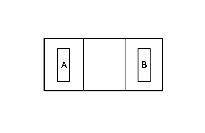
Connector Part Information |
| ||||||
Pin | Wire Color | Circuit No. | Function | ||||
A | RED/BLU | AP802 | Courtesy Lamps Supply Voltage | ||||
B | BLK | F72 | IP Compartment Lamp Switch Signal | ||||

| |||||||
|---|---|---|---|---|---|---|---|
Connector Part Information |
| ||||||
Pin | Wire Color | Circuit No. | Function | ||||
A | BLK | F71 | Ground to G103 | ||||
B | BLK | F72 | IP Compartment Lamp Switch Signal | ||||

| |||||||
|---|---|---|---|---|---|---|---|
Connector Part Information |
| ||||||
Pin | Wire Color | Circuit No. | Function | ||||
1 | BRN/RED | XA810 | Relay Control | ||||
BRN/RED | XA811 | Relay Control | |||||
2 | -- | -- | Not Used | ||||
3 | RED/WHT | AM811 | Exterior Lamp Power | ||||
4 | YEL | B50 | Low Beam Supply Voltage | ||||
5 | RED | A814 | B+ from Fuse V3 | ||||
| |||||||
|---|---|---|---|---|---|---|---|
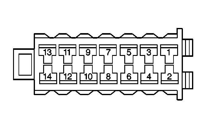
Connector Part Information |
| ||||||
Pin | Wire Color | Circuit No. | Function | ||||
1 | BLK/RED | FA888 | Switched Battery Positive Voltage | ||||
2 | RED/BLU | AP805 | Courtesy Lamps Supply Voltage | ||||
3 | GRY/BLK | RF75 | Park Lamp Supply voltage | ||||
4 | BRN | X6 | Fog Lamp Supply Voltage | ||||
5 | RED | A831 | B+ from Fuse #29 | ||||
6 | BLK | F805 | Ground to G103 | ||||
7 | BRN/PPL | XY800 | Delayed Interior Lamp Relay Control | ||||
8 | BLK/BLU | FP28 | Fog Lamp Switch Signal | ||||
9 | BRN/PPL | XY801 | Interior Lamp Relay Control | ||||
10 | BRN | X820 | Ignition Voltage from Fuse #15 | ||||
11 | BRN/BLU | XP810 | Battery Guard Signal | ||||
12 | RED | A821 | B+ from Fuse #8 | ||||
13 | BRN/BLU | XP803 | Rear Compartment Open Signal | ||||
14 | RED | A600 | Low Power Drive Signal | ||||

| |||||||
|---|---|---|---|---|---|---|---|
Connector Part Information |
| ||||||
Pin | Wire Color | Circuit No. | Function | ||||
1 | BRN/WHT | XM810 | Relay Control | ||||
BRN/WHT | XM815 | Relay Control | |||||
2 | -- | -- | Not Used | ||||
3 | RED/WHT | AM810 | Exterior Lamp Power | ||||
RED/WHT | AM811 | Exterior Lamp Power | |||||
4 | GRY/GRN | RU812 | Park Lamp Supply Voltage | ||||
5 | RED | A813 | B+ from Fuse V3 | ||||
| |||||||
|---|---|---|---|---|---|---|---|
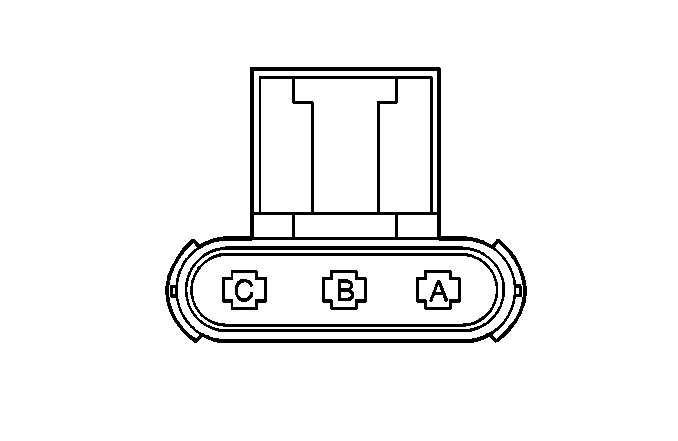
Connector Part Information |
| ||||||
Pin | Wire Color | Circuit No. | Function | ||||
A | BLK | F12 | Ground to G103 | ||||
B | GRY/BLK | RF3 | Park Lamp Signal | ||||
C | BLK/WHT | FM2 | Park Lamp Signal | ||||

| |||||||
|---|---|---|---|---|---|---|---|
Connector Part Information |
| ||||||
Pin | Wire Color | Circuit No. | Function | ||||
A | BLK | F16 | Ground to G103 | ||||
B | GRY/RED | RA3 | Park Lamp Signal | ||||
C | BLK/GRN | FU2 | Park Lamp Signal | ||||

| |||||||
|---|---|---|---|---|---|---|---|
Connector Part Information |
| ||||||
Pin | Wire Color | Circuit No. | Function | ||||
1 | BLK/WHT | FM1 | Ground | ||||
2 | GRY/GRN | RU2 | Lamp ON Signal | ||||

| |||||||
|---|---|---|---|---|---|---|---|
Connector Part Information |
| ||||||
Pin | Wire Color | Circuit No. | Function | ||||
1 | BLK/GRN | FU1 | Ground | ||||
2 | GRY/GRN | RU3 | Lamp ON Signal | ||||
| |||||||
|---|---|---|---|---|---|---|---|
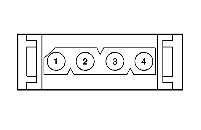
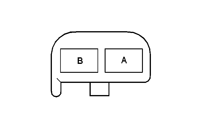
Connector Part Information |
| ||||||
Pin | Wire Color | Circuit No. | Function | ||||
1 | RED | A401 | B+ from Fuse #12 | ||||
2 | BLK/YEL | FB101 | Brake Lamp Supply Voltage | ||||
3 | BRN | X120 | B+ from Fuse #2 | ||||
4 | BLK/BRN | FX102 | RTSI Signal | ||||
| |||||||
|---|---|---|---|---|---|---|---|
Connector Part Information |
| ||||||
Pin | Wire Color | Circuit No. | Function | ||||
A | BLK | F3 | Ground to G103 | ||||
B | RED/BLU | AP3 | Courtesy Lamps Supply Voltage | ||||

| |||||||
|---|---|---|---|---|---|---|---|
Connector Part Information |
| ||||||
Pin | Wire Color | Circuit No. | Function | ||||
A | BLK | F1 | Ground to G103 | ||||
B | RED/BLU | AP1 | B+ from Multifunction Relay | ||||
| |||||||
|---|---|---|---|---|---|---|---|
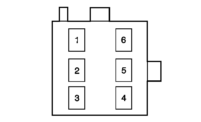
Connector Part Information |
| ||||||
Pin | Wire Color | Circuit No. | Function | ||||
1 | BLK | F125 | Ground to G400 | ||||
2 | BLK/YEL | FB6 | Stop Lamp Signal | ||||
3 | BRN/WHT | XM101 | Hazard Flasher Signal | ||||
4 | -- | -- | Not Used | ||||
5 | GRY/BLK | RF4 | Lamp ON Signal | ||||
6 | BLU/WHT | FM20 | Left Turn Signal | ||||

| |||||||
|---|---|---|---|---|---|---|---|
Connector Part Information |
| ||||||
Pin | Wire Color | Circuit No. | Function | ||||
1 | BLK | F25 | Ground to G400 | ||||
2 | BLK/YEL | FB2 | Stop Lamp Signal | ||||
3 | BRN/WHT | XM102 | Hazard Flasher Signal | ||||
4 | -- | -- | Not Used | ||||
5 | GRY/RED | RA4 | Lamp ON Signal | ||||
6 | BLK/GRN | FU20 | Right Turn Signal | ||||

| |||||||
|---|---|---|---|---|---|---|---|
Connector Part Information |
| ||||||
Pin | Wire Color | Circuit No. | Function | ||||
1 | -- | -- | Not Used | ||||
2 | BRN/WHT | XM200 | Hazard Flasher Signal | ||||
3 | -- | -- | Not Used | ||||
4 | BLK | F12 | Ground to G103 | ||||
5 | -- | -- | Not Used | ||||
6 | BLU | P3 | Ignition Voltage | ||||
7 | -- | -- | Not Used | ||||
8 | BLK/WHT | FM22 | Hazard Flasher Signal | ||||
BLK/WHT | FM91 | Hazard Flasher Signal | |||||
9 | -- | -- | Not Used | ||||
| |||||||
|---|---|---|---|---|---|---|---|
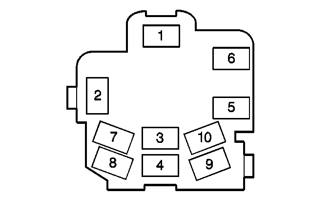
Connector Part Information |
| ||||||
Pin | Wire Color | Circuit No. | Function | ||||
1 | YEL | B905 | B+ from Fuse #31 | ||||
2 | WHT | M3 | High Beam ON/OFF Signal | ||||
3 | YEL | B800 | B+ from Fuse #31 | ||||
YEL | B905 | B+ from Fuse #31 | |||||
4 | BLK/WHT | FM91 | Turn Signal Flasher Signal | ||||
5 | RED | A8 | B+ from Fuse #8 | ||||
6 | -- | -- | Not Used | ||||
7 | GRY/RED | RA999 | RH Cornering Lamp Supply Voltage | ||||
8 | BLK/GRN | FU1 | RH Turn Lamp Supply Voltage | ||||
9 | BLK/WHT | FM1 | LH Turn Lamp Supply Voltage | ||||
10 | GRY/BLK | RH999 | LH Cornering Lamp Supply Voltage | ||||
