- Turn the steering wheel so that the vehicle's wheels are pointing straight ahead.
- Turn OFF the ignition.
- Remove the key from the ignition switch.
- Connect the inflatable restraint side impact module - RF connector.
- Install the connector position assurance (CPA) to the side impact module - RF connector.
- Connect the seat belt pretensioner - RF connector to connector C316.
- Install the RH outer seat track cover.
- Connect the inflatable restraint side impact module - LF connector.
- Install the CPA to the side impact module - LF connector.
- Connect the seat belt pretensioner - LF connector to connector C315.
- Install the LH outer seat track cover.
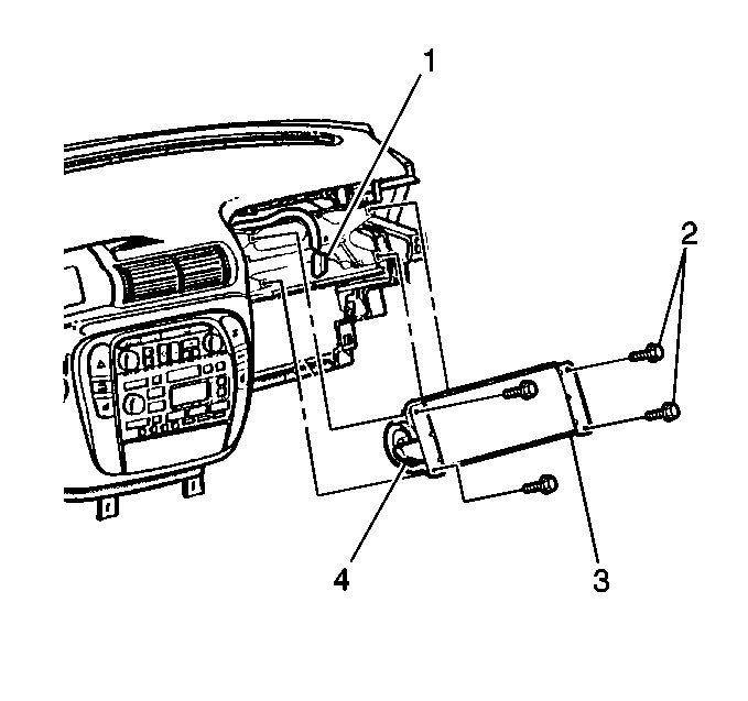
- Connect the inflatable restraint IP module connector (1).
- Install the CPA to the IP module connector.
- Install the IP module cover. Refer to SIR Module Cover Replacement .
- Connect the inflatable restraint steering wheel module 2-way connector to the inflatable restraint steering wheel module.
- Install the connector position assurance (CPA) to the inflatable restraint steering wheel module 2-way connector.
- Install the inflatable restraint steering wheel module to the steering wheel.
- Install the two TORX® screws to the back of the steering wheel.
- Staying well away from all inflator modules and seat belt pretensioners, turn ON the ignition.
- Perform Diagnostic System Check - SIR if the AIR BAG indicator does not operate as described.

Important: Power for the SIR system is fed directly through the ignition switch. The key must remain removed until the SIR enabling procedure requires that the ignition be turned ON.

Notice: Use the correct fastener in the correct location. Replacement fasteners must be the correct part number for that application. Fasteners requiring replacement or fasteners requiring the use of thread locking compound or sealant are identified in the service procedure. Do not use paints, lubricants, or corrosion inhibitors on fasteners or fastener joint surfaces unless specified. These coatings affect fastener torque and joint clamping force and may damage the fastener. Use the correct tightening sequence and specifications when installing fasteners in order to avoid damage to parts and systems.
Tighten
Tighten the screws to 8 N·m (72 lb in).
| 19.1. | The AIR BAG indicator will flash seven times. |
| 19.2. | The AIR BAG indicator will then turn OFF. |
