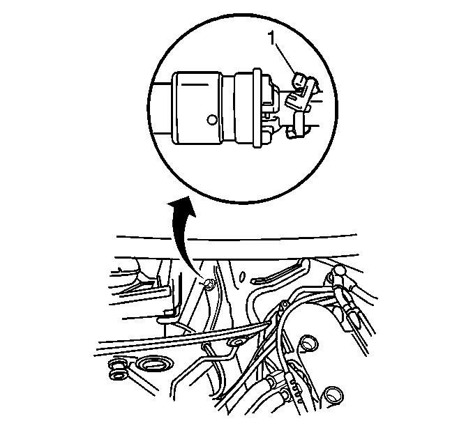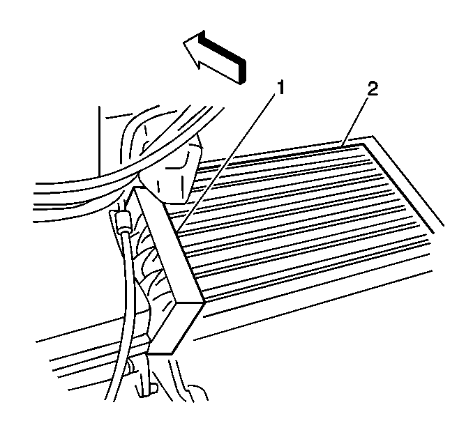
- Install the rubber seal
(1) into the heater core cavity.
- Install the heater core (2).
Use caution to avoid damage to the fins.
Notice: Use the correct fastener in the correct location. Replacement fasteners
must be the correct part number for that application. Fasteners requiring
replacement or fasteners requiring the use of thread locking compound or sealant
are identified in the service procedure. Do not use paints, lubricants, or
corrosion inhibitors on fasteners or fastener joint surfaces unless specified.
These coatings affect fastener torque and joint clamping force and may damage
the fastener. Use the correct tightening sequence and specifications when
installing fasteners in order to avoid damage to parts and systems.
- Install the heater
core retaining screw.
Tighten
Tighten the screws to 1.5 N·m (13 lb in).
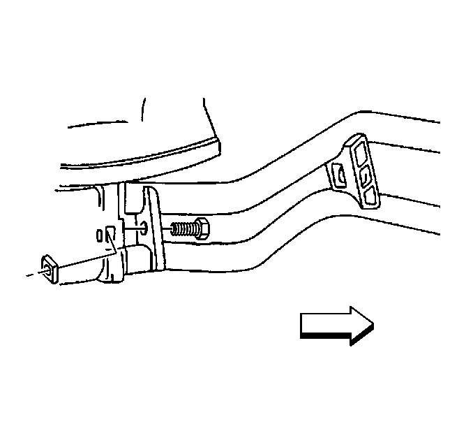
- Install the heater core
inlet and outlet pipes:
| • | Lightly lubricate the O-rings with coolant. |
- Install the heater core inlet and outlet pipe retaining bracket
screw.
Tighten
Tighten the screw to 5 N·m (44 lb in).
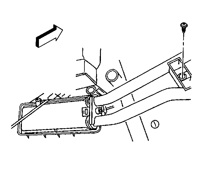
- Install the heater core
pipe bracket.
- Install the heater core pipe bracket screw.
Tighten
Tighten the screw to 1.5 N·m (13 lb in).
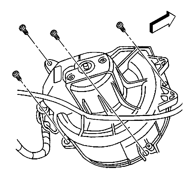
- Install the blower motor
housing with the motor.
- Install the blower motor housing screws.
Tighten
Tighten the screws to 4 N·m (35 lb in).
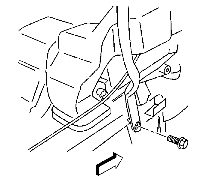
- Install the IP support
bracket.
- Install the IP support bracket bolts.
Tighten
Tighten the bolts to 22 N·m (16 lb ft).
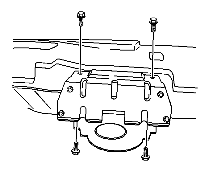
- Install the SIR mounting
bracket.
- Install the SIR mounting bracket bolts.
Tighten
Tighten the bolts to 16 N·m (12 lb ft).
- Install the IP carrier. Refer to
Instrument Panel Carrier Replacement
in Instrument Panel, Gages and Console.
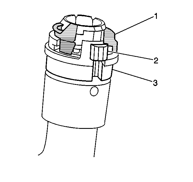
- Install the heater hose
quick connects to the heater core pipe connections:
| • | Discard green assembly marker (1) if not attached to the quick
connect. |
| • | Inspect that the quick connects are fully seated. |
| • | Squeeze the locking tabs (2) and push the retaining sleeve (3)
into the locked position. |
| • | Close the access door near the pollen filter and lower the air
inlet screen on the passenger side. |
- Fill the cooling system. Refer to
Cooling System Draining and Filling
in Engine Cooling.
