Removal Procedure
- Raise and suitably support the vehicle. Refer to Lifting and Jacking the Vehicle in General Information.
- Remove the exhaust muffler heat shields. Refer to Exhaust Heat Shield Replacement in Engine Exhaust.
- Remove the propeller shaft. Refer to Two-Piece Propeller Shaft Replacement in Propeller Shaft.
- Measure the length of the exposed shaft thread from the nut to the end of the shaft.
- Record the measurement.
- Remove the parking brake shoe adjuster nut (1) from the parking brake lever shaft (2).
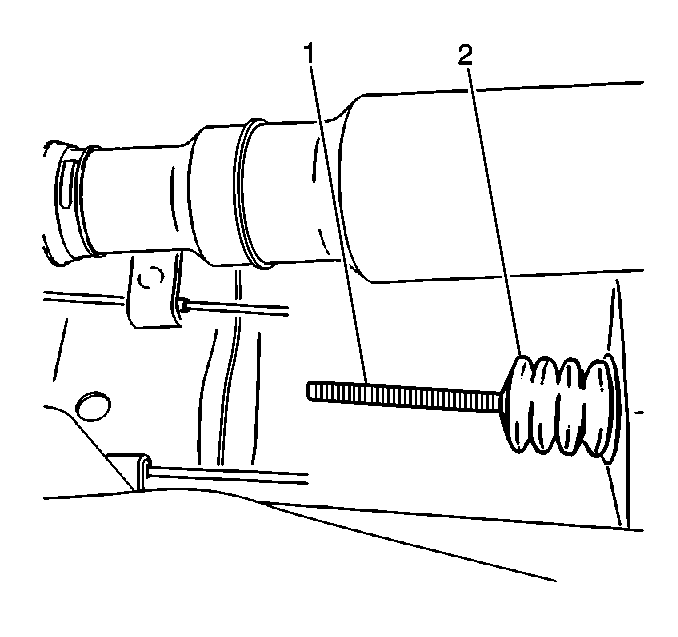
- Remove the parking brake cable guide from the parking brake lever shaft.
- Remove the parking brake cable adjuster link boot (1) from the parking brake lever shaft (2).
- Lower the vehicle.
- Remove the upper section of the center console. Refer to Console Replacement in Instrument Panel, Gauges and Console.
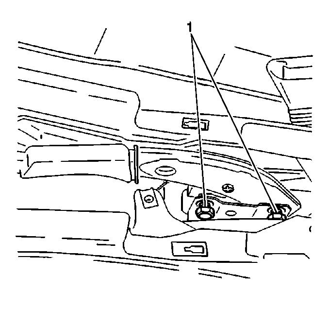
- Remove the parking brake lever bolts (1) from the lever.
- Slightly lift the lever assembly from the underbody.
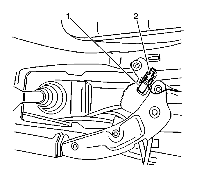
- Disconnect the parking brake switch connector (1) from the parking brake switch (2).
- Remove the parking brake lever.
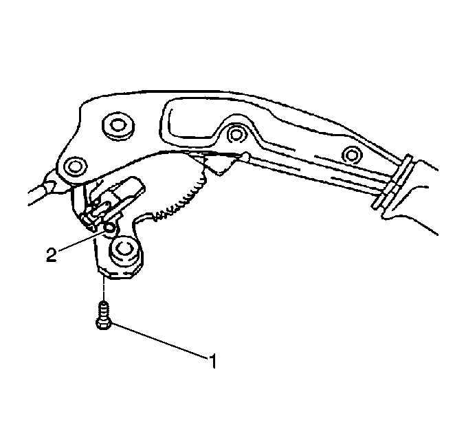
- Remove the parking brake switch bolt (1) from the parking brake indicator switch (2).
- Remove the parking brake switch.
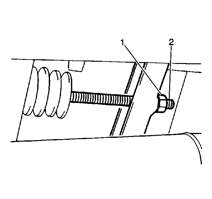
Important: Clean and lubricate the exposed threads of the shaft before attempting to turn the adjuster nut.
Installation Procedure
- Install the parking brake switch.
- Install the parking brake switch bolt (1).
- Connect the parking brake switch connector (1) to the parking brake switch (2).
- Install the parking brake lever.
- Install the parking brake lever bolts (1).
- Install the section of the center console. Refer to Console Replacement in Instrument Panel, Gauges and Console.
- Raise and suitably support the vehicle. Refer to Lifting and Jacking the Vehicle in General Information.
- Install the parking brake cable adjuster link boot (1) to the parking brake lever shaft (2).
- Install the parking brake cable guide.
- Install the parking brake shoe adjuster nut (1) to the parking brake lever shaft (2).
- Adjust the parking brake shoe adjuster nut (1) to the recorded measurement from the installation procedure.
- Install the propeller shaft. Refer to Two-Piece Propeller Shaft Replacement in Propeller Shaft.
- Test the parking brake operation. Refer to Park Brake Adjustment .
- Install the exhaust muffler heat shields. Refer to Exhaust Heat Shield Replacement in Engine Exhaust.
- Lower the vehicle.

Notice: Use the correct fastener in the correct location. Replacement fasteners must be the correct part number for that application. Fasteners requiring replacement or fasteners requiring the use of thread locking compound or sealant are identified in the service procedure. Do not use paints, lubricants, or corrosion inhibitors on fasteners or fastener joint surfaces unless specified. These coatings affect fastener torque and joint clamping force and may damage the fastener. Use the correct tightening sequence and specifications when installing fasteners in order to avoid damage to parts and systems.
Tighten
Tighten the parking brake switch bolt to 3 N·m (27 lb in).


Tighten
Tighten the parking brake lever bolts to 20 N·m (15 lb ft).


