Removal Procedure
- Remove the intake air resonator. Refer to Intake Air Resonator Replacement in Engine Controls - 3.0L.
- Remove the intake plenum. Refer to Intake Plenum Replacement .
- Raise and support the vehicle. Refer to Lifting and Jacking the Vehicle in General Information.
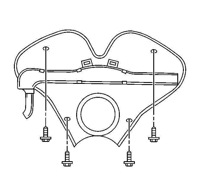
- Remove the 4 engine splash shield bolts.
- Remove the engine splash shield.
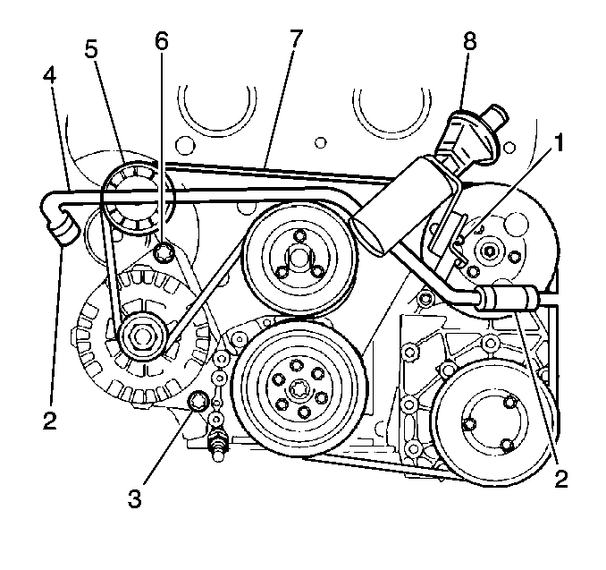
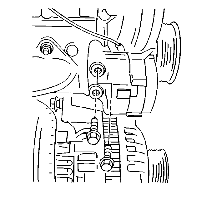
- Counterhold the generator bolt on the back side of the generator to remove the AIR injection crossover pipe bracket nut (6) from the generator bolt.
- Remove the AIR crossover pipe bushing nut (1), located on the left side of the engine, from the bracket.
- Remove the AIR crossover pipe clamps from the rubber hose.
- Remove the AIR crossover pipe from the AIR pipe hoses (2).
- Lower the vehicle.
- Remove the AIR check valve (8) hose clamp.
- Remove the AIR check valve hose from the check valve.
- Remove the AIR crossover pipe (4).
- Loosen the water pump pulley bolts.
- Loosen the power steering pump pulley bolts.
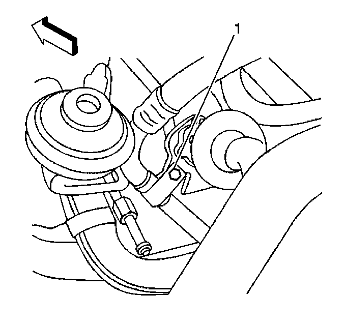
- Remove the A/C compressor hose support strap bolt (1) from the AIR injection crossover bracket.
- Remove the accessory drive belt.
- Pull forward and remove the wiring harness channel cover.
- Release the plastic retaining tabs on the wiring harness channel extension from the right lower side of the wiring harness channel and pull forward to remove.
- Remove the wiring harness from the channel.
- Remove the water pump pulley bolts.
- Remove the water pump pulley.
- Remove the power steering pump pulley bolts.
- Remove the power steering pump pulley.
- Remove the accessory drive belt tensioner bolts.
- Remove the accessory drive belt tensioner.
- Remove the front timing belt cover bolts.
- Remove the front timing belt cover.
- Transfer wiring harness channel if applicable.
- Inspect the sealing strip on the outer edge of the front timing belt cover for cracks and/or tears. Replace as necessary.


Important: Use caution when releasing the retaining tabs to reduce the risk of breakage when removing the wiring harness channel cover.
Note the wiring harness routing.


Installation Procedure
- Install the front timing belt cover.
- Install the front timing belt cover bolts.
- Install the accessory drive belt tensioner.
- Install the accessory drive belt tensioner bolts.
- Install the power steering pump pulley.
- Install the power steering pump pulley bolts.
- Install the water pump pulley.
- Route the wiring harness into the wiring harness channel.
- Install the wiring harness channel cover.
- Install the wiring harness channel extension to the right lower side of the wiring harness channel.
- Install the accessory drive belt.
- Install the A/C compressor hose support strap bolt (1) to the AIR injection crossover bracket.
- Install AIR crossover pipe (4).
- Install the AIR check valve (8) to the AIR hose.
- Install the AIR check valve (8) hose clamp.
- Raise the vehicle.
- Install the AIR crossover pipe (4) to the AIR pipe hoses (2).
- Install the AIR crossover pipe clamps to the AIR pipe hoses.
- Install the AIR crossover pipe bushing nut (1).
- Counterhold the generator bolt on the back side of the generator to remove the AIR injection crossover pipe support bracket nut (6) from the generator bolt.
- Install the AIR injection crossover pipe bracket (6) nut to the generator bolt.
- Install the engine splash shield.
- Install the 4 engine splash shield bolts.
- Lower the vehicle.
- Install the intake plenum. Refer to Intake Plenum Replacement .
- Install the intake air resonator. Refer to Intake Air Resonator Replacement in Engine Controls - 3.0L.

Notice: Use the correct fastener in the correct location. Replacement fasteners must be the correct part number for that application. Fasteners requiring replacement or fasteners requiring the use of thread locking compound or sealant are identified in the service procedure. Do not use paints, lubricants, or corrosion inhibitors on fasteners or fastener joint surfaces unless specified. These coatings affect fastener torque and joint clamping force and may damage the fastener. Use the correct tightening sequence and specifications when installing fasteners in order to avoid damage to parts and systems.
Tighten
Tighten the front timing belt cover bolts to 8 N·m (71 lb in).

Tighten
Tighten the accessory drive belt tensioner bolts to 40 N·m
(30 lb ft).
Tighten
Tighten the power steering pump pulley to 20 N·m (15 lb ft).
Tighten
Tighten the water pump pulley bolts to 8 N·m (71 lb in).

Tighten
Tighten the A/C compressor hose support strap bolt to 8 N·m
(71 lb in).

Tighten
Tighten the AIR crossover pipe bushing nut to 12 N·m (108 lb in).
Tighten
Tighten the generator bolt to 40 N·m (30 lb ft).
Tighten
Tighten the engine splash shield bolts to 10 N·m (89 lb in).
