You can diagnose all of the sensors and most of the input circuits with a scan tool. Within this section is a short description of how to use a scan tool wherever possible to diagnose these circuits. You can also use the scan tool to compare the values for an engine that is running normally with the engine you are diagnosing.
A/C Request Signal
The A/C request circuit signals the engine control module (ECM) when you select an A/C mode at the A/C control head. The ECM uses this information in order to enable the A/C compressor clutch and in order to adjust the idle speed before turning ON the A/C clutch. If this signal is not available to the ECM, the A/C compressor will be inoperative.
A/C Load Signal
The A/C load circuit signals the ECM when the A/C compressor system is under an excessive load during, for example, any high ambient conditions. If the system pressure exceeds 1,200 kPa (174 psi), the ECM will detect this condition and increase the idle speed by about 50 RPM in order to compensate for the excess load.
Bank 1 and Bank 2 Knock Sensors (KS)
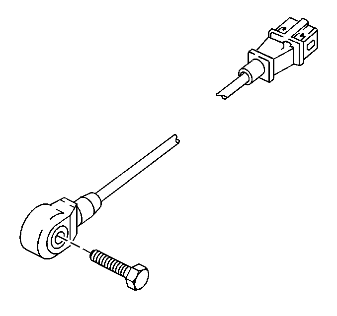
The knock sensor (KS) system detects engine detonations. The knock sensor module is employed in the engine control module (ECM). The ECM will retard the spark timing based on the signals from the KS module. The knock sensors produce an AC voltage that is sent to the KS module. The amount of the AC voltage produced is proportional to the amount of knock.
The control module reads the voltage of the sensor during the 45 degrees after cylinder 2, 4, or 6 has fired and the voltage of the sensor during the 45 degrees after cylinder 1, 3, or 5 has fired.
If knock occurs in any of the cylinders, the ignition will be retarded by 3 degrees for that particular cylinder. If the knocking then stops, the ignition will be restored to what it was before in steps of 0.75 degrees.
Should knocking continue in the same cylinder in spite of the ignition being retarded, the control module will retard the ignition an additional step of 3 degrees, and so on, up to a maximum of 12.75 degrees. The ignition will also be retarded at high ambient temperatures in order to counteract knocking tendencies provoked by high intake air temperatures.
Should either the bank 1 or the bank 2 sensor fail to work, or should a break in the circuit occur, no continuity, the ignition timing will then use a default strategy that will retard the ignition much more than normal.
Camshaft Position (CMP) Sensor
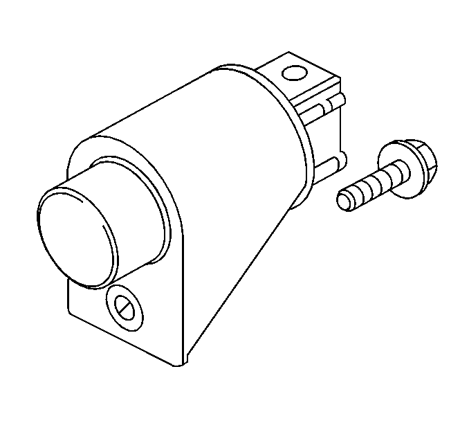
The camshaft position (CMP) sensor works in conjunction with a single tooth reluctor wheel on the bank 2 intake camshaft. The engine control module (ECM) pulls up the CMP sensor signal circuit to 5 volts and monitors this voltage. As the reluctor wheel tooth rotates past the sensor, the sensors internal circuitry pulls the signal circuit to ground, creating a square wave signal used by the ECM. The reluctor wheel tooth covers 180 degrees of the camshaft circumference. This causes the CMP signal voltage to transition once per crankshaft revolution. This signal, when combined with the crankcase position (CKP) sensor signal, enables the ECM to determine exactly when cylinder #1 is on a firing stroke. The ECM can then properly synchronize the ignition system, the fuel injectors, and the knock control. Note that as long as the CKP signal is available, the engine can start even if there is no CMP sensor signal. The ECM will default to non-sequential fuel injector operation. The DTC P0340-CMP sensor circuit indicates that the ECM has detected a CMP system fault.
Crankshaft Position (CKP) Sensor
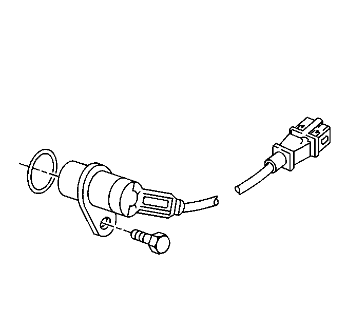
The crankshaft position (CKP) sensor works in conjunction with a 58 tooth reluctor wheel on the crankshaft. The engine control module (ECM) monitors the voltage between the CKP sensor signal circuits. As each reluctor wheel tooth rotates past the sensor, the sensor creates an analog signal. This analog signal is processed by the ECM. The reluctor wheel teeth are 6 degrees apart. Having only 58 teeth leaves a 12 degree span that is uncut. This creates a signature pattern that enables the ECM to determine the crankshaft position. The ECM can determine which two cylinders are approaching the top center based on the CKP signal alone. The camshaft position (CMP) sensor signal is used in order to determine which of the two cylinders is on a firing stroke. The ECM can then properly synchronize the ignition system, the fuel injectors, and the knock control. This sensor is also used in order to detect misfire. Refer to DTC P0300 for information on misfire detection. The DTC P0335-CKP sensor circuit indicates that the ECM has detected a CKP system fault.
Engine Coolant Temperature (ECT) Sensor
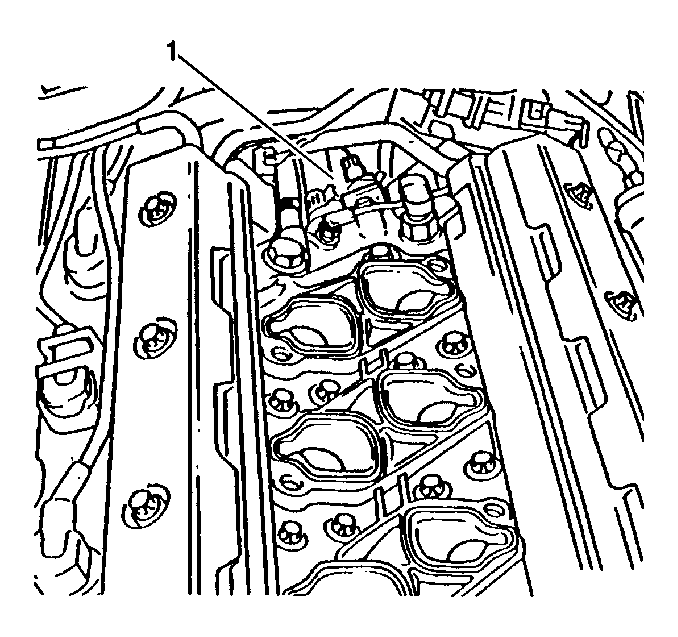
The engine coolant temperature (ECT) sensor (1) contains a thermistor which changes resistance based on the temperature. The ECT sensor is located in the coolant crossover pipe at the center rear of the engine. The ECT sensor has a signal circuit and a ground circuit. The engine control module (ECM) applies a voltage, about 5.0 volts, on the signal circuit to the sensor. The ECM monitors the changes in this voltage that are caused by the changes in the resistance of the sensor in order to determine the engine coolant temperature.
When the engine coolant is cold, the sensor resistance is high, and the ECM will sense a high signal voltage or low temperature. When the engine coolant is warm, the sensor resistance is low. This causes the ECM to sense a low signal voltage or high temperature.
The scan tool displays engine coolant temperature in degrees. After engine startup, the temperature should rise steadily to about 90°C (194°F) then stabilize when the thermostat opens. If the engine has not been run for several hours or overnight, the engine coolant temperature and intake air temperature displays should be close to each other. When the ECM detects a malfunction in the ECT sensor circuit, the following DTCs will set:
| • | DTC P0115--ECT sensor circuit |
| • | DTC P0116--ECT sensor circuit performance |
Fuel Tank Pressure Sensor
The fuel tank pressure sensor (FTP) mounts to the sending unit at the top of the fuel tank. The FTP sensor measures the pressure changes within the evaporative emission (EVAP) system. The fuel tank pressure sensor has a 5-volt reference circuit, a ground circuit, and a signal circuit.
The fuel tank pressure sensor contains a diaphragm that changes resistance based on pressure. When the EVAP system pressure is low, during purge, the sensor output voltage is low. When the system pressure is high, the sensor output voltage is high. The signal from this sensor provides feedback to the ECM on the EVAP system operation. The ECM programming contains information on expected EVAP system behavior under various operating conditions. The ECM monitors the EVAP system pressure. If the fuel tank pressure sensor signal is outside of the normal operating range, then DTC P0450--fuel tank pressure (FTP) sensor circuit will set.
If the fuel tank pressure sensor signal differs from an expected result during an EVAP system test, caused by either a sensor problem or an actual EVAP system problem, the following DTCs can set:
| • | DTC P0440--EVAP system performance |
| • | DTC P0442--Evaporative emission (EVAP) system small leak detected |
| • | DTC P0455--Evaporative emission (EVAP) system leak detected |
Heated Oxygen Sensors (HO2S) - Pre-Catalyst (Front)
The wide band heated oxygen sensor (HO2S) measures the amount of oxygen in the exhaust stream more quickly and accurately than the switching style HO2S. The wide range HO2S sensor functions more like an air fuel sensor. The wide band sensor consists of an oxygen sensing cell, an oxygen pumping cell, and a heater. The exhaust gas sample passes through a diffusion gap between the sensing cell and the pumping cell. The engine control module (ECM) supplies a signal voltage to the HO2S and uses this voltage as a reference to the amount of oxygen in the exhaust system. An electronic circuit within the ECM controls the pump current through the oxygen pumping cell in order to maintain a constant signal voltage. The ECM monitors the voltage variation on the signal circuit and attempts to keep the voltage constant by increasing or decreasing the amount of current flow or reversing the direction of the current flow to the pumping cell. By measuring the direction and amount of current required to maintain the signal voltage, the ECM can determine the concentration of oxygen in the exhaust. The signal voltage is displayed as a lambda value. A lambda value of 1 is equal to a stoichiometric air fuel ratio of 14.7:1. Under normal operating conditions, the lambda value will remain around 1. When the system is lean, the oxygen level will be high and the lambda signal will be high or more than 1. When the oxygen level is low, the lambda signal will be low or less than 1. The ECM uses this information to maintain the proper air/fuel ratio.
Heated Oxygen Sensors (HO2S) - Post-Catalyst (Rear)
The heated oxygen sensor (HO2S) produces a voltage that varies between 100-900 mV under normal operating conditions. The engine control module (ECM) produces a bias voltage on the heated oxygen sensor (HO2S) signal circuit of 420-480 mv. The reference ground for the sensor is provided through the ECM. The ECM monitors the signal voltage to determine if the exhaust is lean or rich. The oxygen sensor voltage is high when the exhaust is rich, and low when the exhaust is lean. The ECM constantly monitors the HO2S signal during the Closed Loop operation.
Catalyst Monitoring
A 3-way catalytic converter (TWC) is used to control emissions of hydrocarbons (HC), carbon monoxide (CO), and oxides of nitrogen (NOx). The catalyst within the converter promotes a chemical reaction that oxidizes the HC and the CO present in the exhaust gas, converting the HC and the CO into harmless water vapor and carbon dioxide. The catalyst also reduces NOx, converting the NOx to nitrogen. The engine control module (ECM) monitors this process by using the bank 1 heated oxygen sensor (HO2S) 2 and the bank 2 HO2S 2 . The front HO2S produce an output signal that indicates how much oxygen is present in the exhaust gas entering the TWC. The rear HO2S produce an output signal that indicates the oxygen storage capacity of the catalyst. The catalysts oxygen storage capacity indicates the catalysts ability to convert the exhaust gases efficiently.
Intake Air Temperature (IAT) Sensor
The intake air temperature (IAT) sensor contains a thermistor which changes the resistance based on the temperature. The IAT sensor is located in the mass air flow (MAF) sensor. The IAT sensor has a signal circuit and a ground circuit. The engine control module (ECM) applies a voltage, about 5 volts, on the signal circuit to the sensor. The ECM monitors any changes in this voltage caused by changes in the resistance of the sensor in order to determine the intake air temperature.
When the intake air is cold, the sensor resistance is high. Therefore, the ECM will sense a high signal voltage or low temperature. When the intake air is warm, the sensor resistance is low. This causes the ECM to sense a low signal voltage or high temperature.
The scan tool displays the temperature of the air entering the engine. This reading should be close to the ambient air temperature when the engine is cold. The temperature reading should rise as the underhood temperature increases. If the engine has not been run for several hours, overnight, the IAT sensor temperature and the engine coolant temperature (ECT) should be similar.
When the ECM senses a signal voltage outside of the normal operating range of the sensor, DTC P0110 will set.
Mass Air Flow (MAF) Sensor
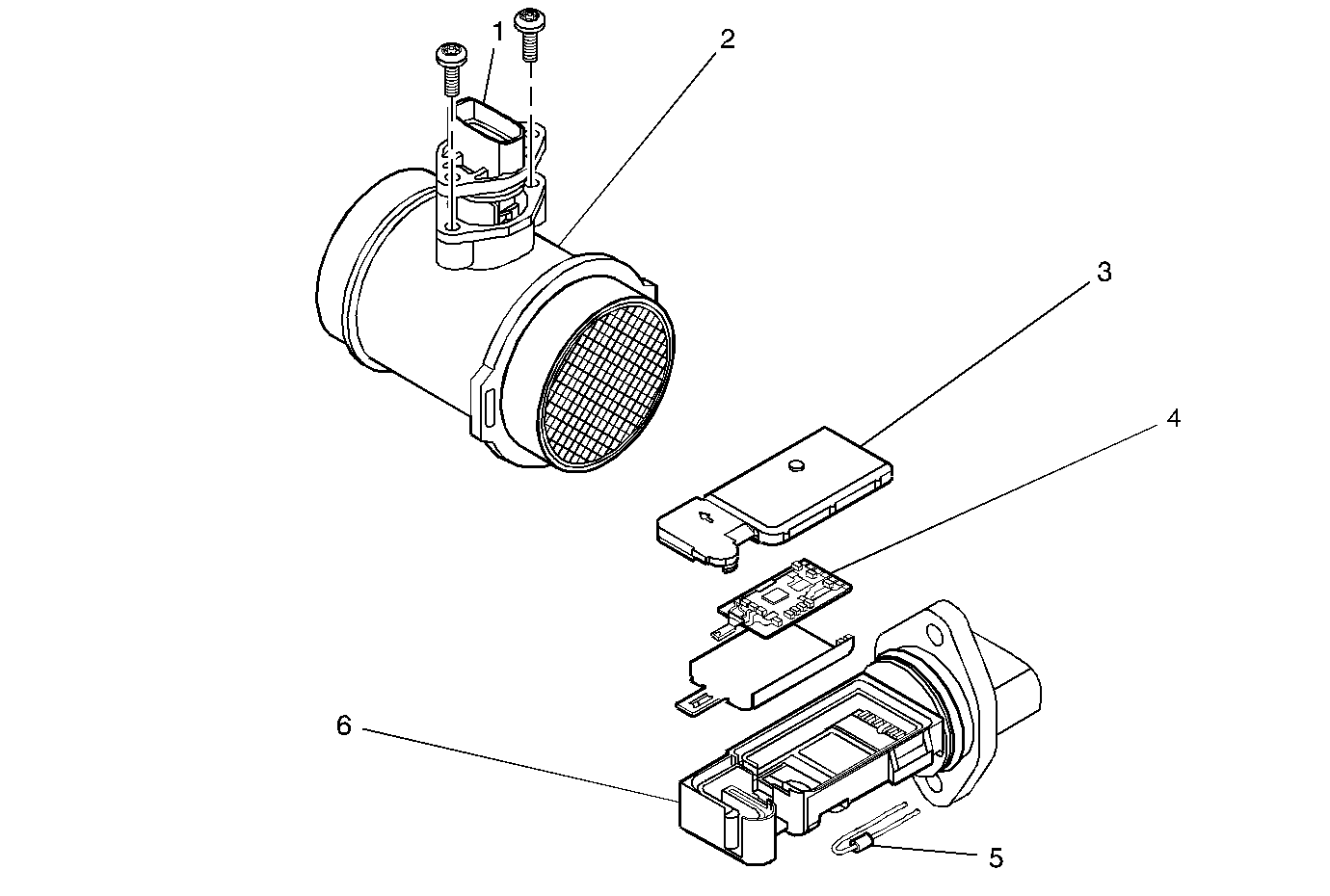
Mass Air Flow Sensor
