GM Service Manual Online
For 1990-2009 cars only
Makes
🢒
Cadillac
🢒
2001
🢒
Catera
🢒
Engine
🢒
Engine Cooling
🢒 Engine Cooling Schematics
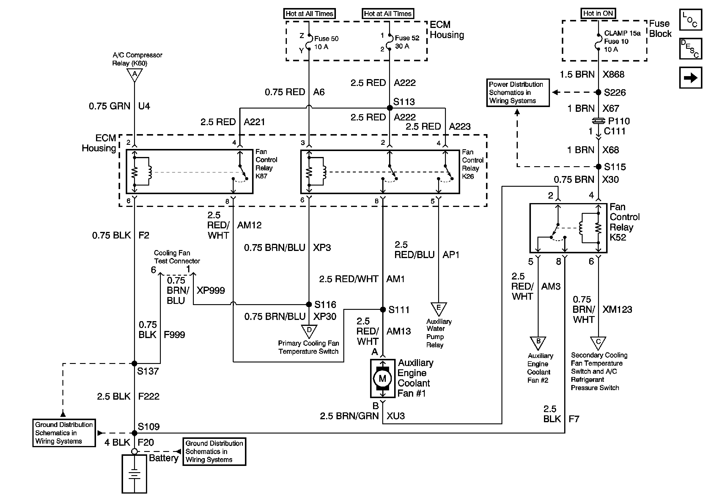
Figure
1:
Auxiliary Engine Coolant Fan #1
Master Electrical Component List
Cooling System Description and Operation
Cooling Fan, Auxiliary Water Pump, and Heater Water Auxiliary Pump
Battery Cable Bus
Battery Cable Bus
Underhood Fuse Block Fuses V1 and V4, and Ignition Switch
Auxiliary Engine Cooling Fan #2
Fuse Block Fuses 10 and 24
Cooling Fan, Auxiliary Water Pump, and Heater Water Auxiliary Pump
Auxiliary Engine Cooling Fan #2
G103 (2 of 8)
G103 (1 of 8)
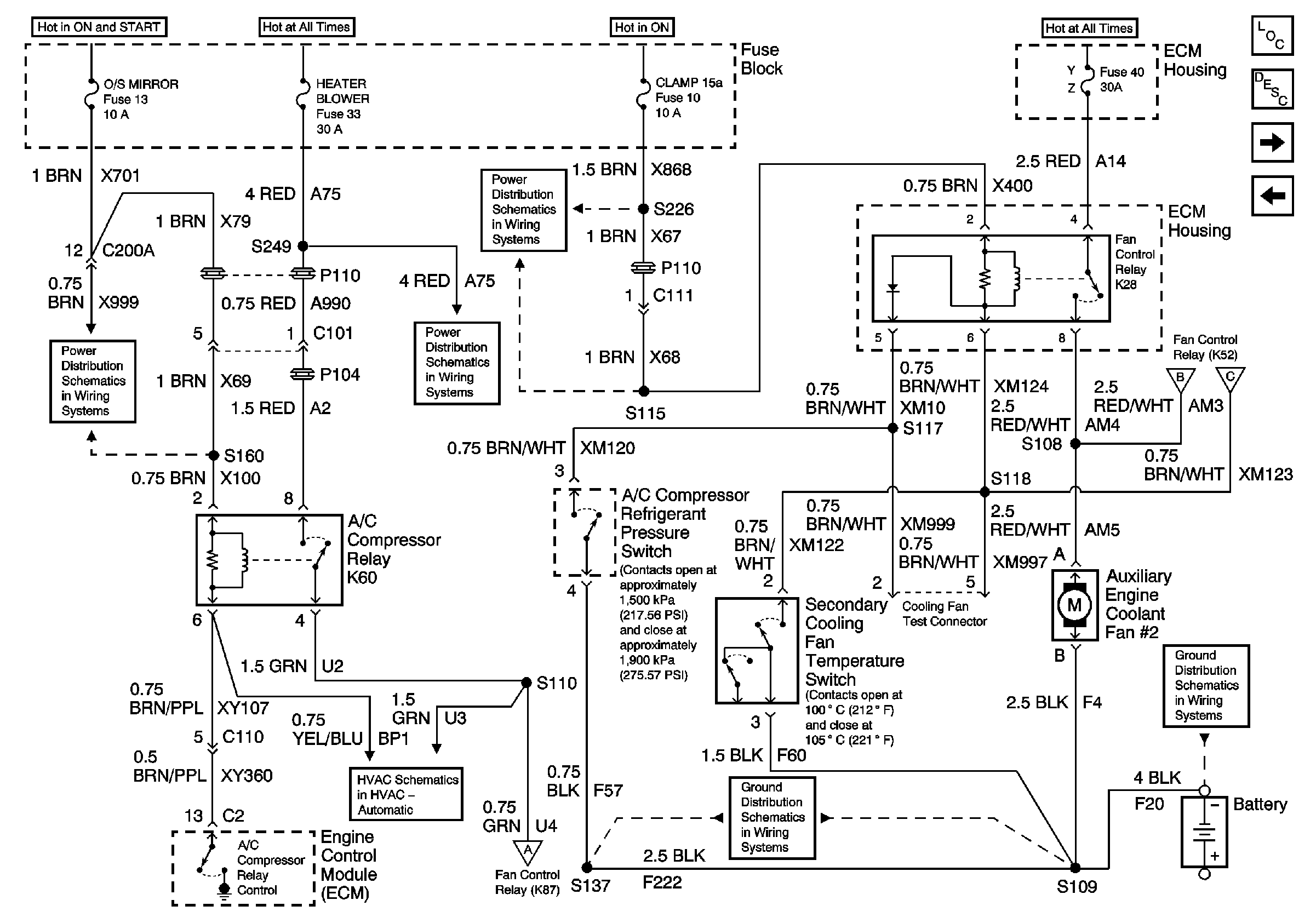
Figure
2:
Cooling Fan, Auxiliary Water Pump, and Heater Water Auxiliary Pump
Master Electrical Component List
Cooling System Description and Operation
Auxiliary Engine Cooling Fan #2
Auxiliary Engine Coolant Fan #1
Battery Cable Bus
Auxiliary Engine Coolant Fan #1
Underhood Fuse Block Fuses V1 and V4, and Ignition Switch
Fuse Block Fuses 10 and 24
G103 (1 of 8)
G103 (2 of 8)
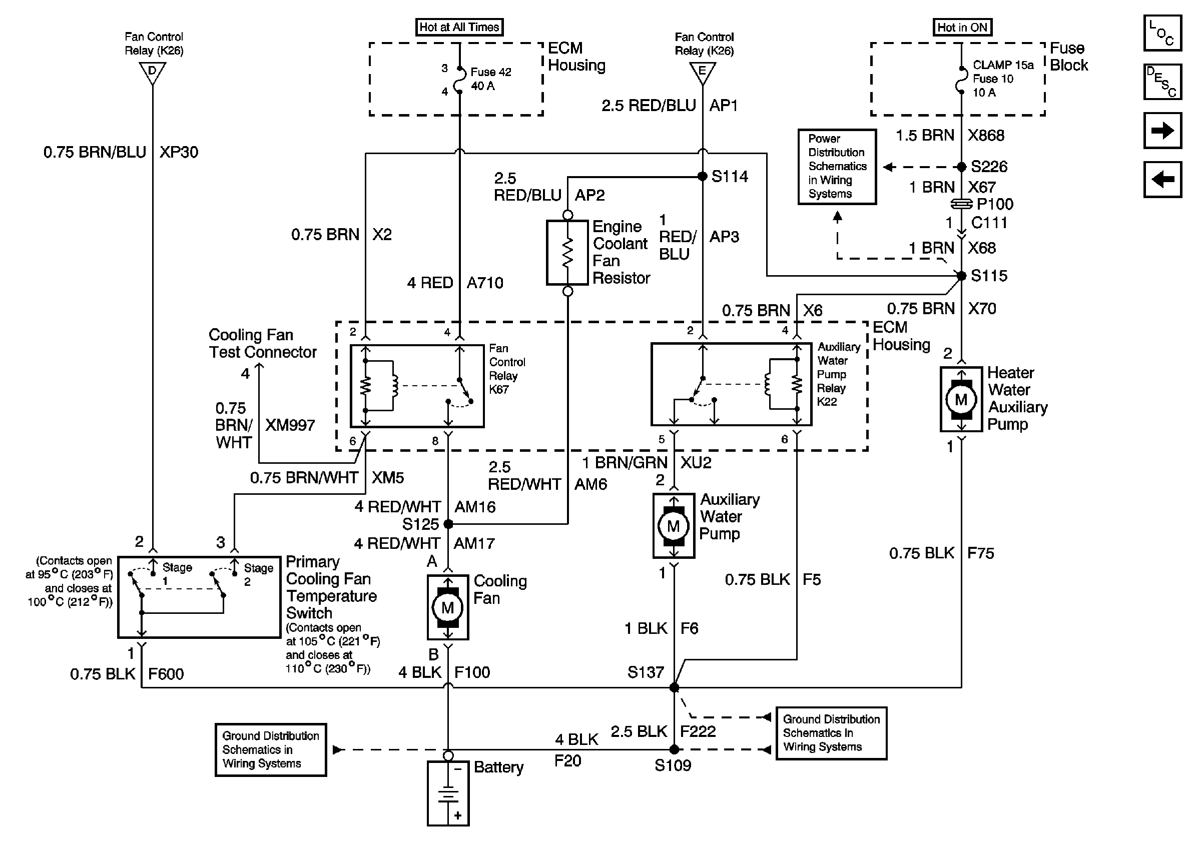
Figure
3:
Auxiliary Engine Coolant Fan #2
Master Electrical Component List
Cooling System Description and Operation
Coolant Level Indicator
Cooling Fan, Auxiliary Water Pump, and Heater Water Auxiliary Pump
Underhood Fuse Block Fuses V1 and V4, and Ignition Switch
Underhood Fuse Block Fuse V6 and Fuse Block Fuses 17, 28, 29, 33, and34
Underhood Fuse Block Fuses V1 and V4, and Ignition Switch
Battery Cable Bus
Fuse Block Fuses 10 and 24
Fuse Block Fuses 3, 13, and 19
Underhood Fuse Block Fuse V6 and Fuse Block Fuses 17, 28, 29, 33, and34
Auxiliary Engine Coolant Fan #1
G103 (1 of 8)
Compressor Controls
Auxiliary Engine Coolant Fan #1
G103 (2 of 8)
Figure
4:
Coolant Level Indicator
Master Electrical Component List
Cooling System Description and Operation
Auxiliary Engine Cooling Fan #2
Fuel, Coolant and Oil Gauges and Indicators
G103 (6 of 8)
G103 (1 of 8)