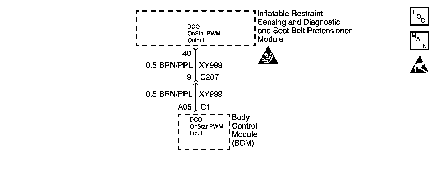
Circuit Description
When you first turn ON the ignition, the inflatable restraint sensing and diagnostic and seat belt pretensioner module (SDM) performs tests to diagnose critical malfunctions within itself. Then, the SDM proceeds with the RESISTANCE MEASUREMENT test to measure the deployment loop resistances to ensure that they are within their respective normal resistance ranges. Upon passing these tests, the energy reserve is charged and the firing transistors are tested. The SDM then goes into the CONTINUOUS MONITORING mode. The SDM is hard-wired to the body control module (BCM) through the deployment commanded output (DCO) circuit. During the CONTINUOUS MONITORING mode, the SDM sends fixed frequency pulses to the BCM. In the event of a collision involving air bag or seat belt pretensioner deployment, the SDM sends higher frequency pulses to the BCM, which in turn sends a Class 2 message to the ONSTAR module. Upon receiving the Class 2 message, the ONSTAR module transmits a deployment commanded output (DCO) signal to the service center via the vehicle's cellular telephone.
Conditions for Running the DTC
When the ignition voltage is within the normal operating voltage range and the SDM is in the CONTINUOUS MONITORING mode, the SDM monitors the DCO circuit in order to detect a leakage current to voltage or an open in the DCO circuit.
Conditions for Setting the DTC
The measured leakage current to voltage or the resistance of the DCO circuit are above a specified value caused by:
| • | A short to voltage in the DCO circuit |
| • | An open or a high resistance in the DCO circuit |
Action Taken When the DTC Sets
The SDM turns ON the AIR BAG warning lamp.
Conditions for Clearing the DTC
| • | You can issue a CLEAR CODES command. |
| • | A history DTC will clear once 255 malfunction free ignition cycles have occurred. |
Diagnostic Aids
An open, high resistance, or a short to voltage in the DCO circuit can cause an intermittent condition. Inspect the DCO circuit carefully for cutting and/or chafing.
Test Description
-
This step checks the SDM wiring harness connector.
-
This step checks the SDM terminals.
-
This step checks the BCM wiring harness connector C1.
-
This step checks the BCM terminals.
-
This step checks for an open or a high resistance in the DCO circuit.
-
This step checks for a short to B+ in the DCO circuit.
-
This step determines if there is a malfunctioning BCM or if there is a malfunctioning SDM.
Step | Action | Value(s) | Yes | No | ||||||
|---|---|---|---|---|---|---|---|---|---|---|
1 | Did you perform A Diagnostic System Check - SIR? | -- | Go to Step 2 | |||||||
Does the SDM wiring harness connector exhibit any signs of corrosion, terminal damage, or poor connections? | -- | Go to Step 3 | Go to Step 5 | |||||||
3 | Replace the SDM wiring harness connector. Refer to Connector Repairs in Wiring Systems. Did you complete the repair? | -- | Go to Step 4 | -- | ||||||
Inspect the SDM terminals for corrosion or damaged terminals. Does the SDM exhibit any signs of corrosion or damaged terminals? | -- | Go to Step 16 | Go to Step 17 | |||||||
5 | Inspect the SDM terminals for corrosion or damaged terminals. Does the SDM exhibit any signs of corrosion or damaged terminals? | -- | Go to Step 16 | Go to Step 6 | ||||||
Does the BCM wiring harness connector C1 exhibit any signs of corrosion, terminal damage, or poor connections? | -- | Go to Step 7 | Go to Step 9 | |||||||
7 | Replace the BCM wiring harness connector C1. Refer to Connector Repairs in Wiring Systems. Did you complete the repair? | -- | Go to Step 8 | -- | ||||||
Inspect the BCM terminals for corrosion or damaged terminals. Does the BCM exhibit any signs of corrosion or damaged terminals? | -- | Go to Step 15 | Go to Step 17 | |||||||
9 | Inspect the BCM terminals for corrosion or damaged terminals. Does the BCM exhibit any signs of corrosion or damaged terminals? | -- | Go to Step 15 | Go to Step 10 | ||||||
Use the J 39200 Digital Multimeter (DMM) to measure the resistance of the DCO circuit. Does the resistance measure less than the specified value? | 0.5 ohms | Go to Step 12 | Go to Step 11 | |||||||
11 | Locate and repair an open or a high resistance in the DCO circuit. Did you complete the repair? | -- | Go to Step 17 | -- | ||||||
Does the voltage measure less than the specified value? | 1 V | Go to Step 14 | Go to Step 15 | |||||||
13 | Locate and repair a short to B+ in the DCO circuit. Did you complete the repair? | -- | Go to Step 17 | -- | ||||||
Does the scan tool indicate that the ONSTAR test flag displays SET and the ONSTAR signal displays OK? | -- | Go to Step 16 | Go to Step 15 | |||||||
15 | Replace the BCM. Refer to Body Control Module Replacement in Body Control System. Did you complete the replacement? | -- | Go to Step 17 | -- | ||||||
16 | Replace the SDM. Refer to Inflatable Restraint Sensing and Diagnostic and Seat Belt Pretensioner Module Replacement . Did you complete the replacement? | -- | Go to Step 17 | -- | ||||||
17 |
Did you complete the action? | -- | -- |
