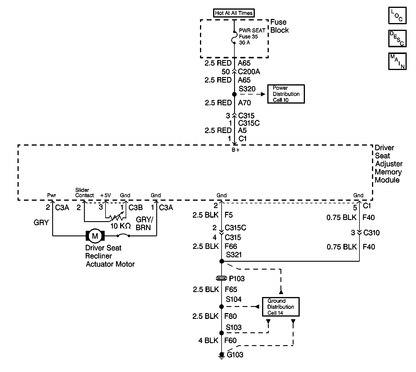
Circuit Description
The memory seat module controls the driver seat recliner adjuster motor by providing voltage and ground to the adjuster motor supply circuits. The direction of seat adjustment is determined by the polarity of the adjuster motor supply circuits. The memory seat module uses position sensors for storing and recalling memory seat position settings. The position sensor is an internal part of the recliner adjuster motor. The memory seat module provides a 5 volt reference and low reference to the recliner position sensor, and monitors the recliner position sensor signal circuit which varies from 0 to 5 volts depending on the seat position.
Conditions for Setting the DTC
DTC 12 will set if:
| • | The driver seat recliner adjuster motor position sensor signal voltage is not within 0.1 to 4.9 volts. |
| • | The recliner adjuster motor is open or shorted. |
| • | The memory seat module is faulty. |
Action Taken When the DTC Sets
DTC 12 will set, and the seat recliner adjuster motor memory operation will be disabled.
Conditions for Clearing the DTC
DTC 12 will be stored as a history code when the fault is no longer present.
Diagnostic Aids
| • | Inspect for mechanical conditions which may prevent the recliner adjuster motor from operating properly. |
| • | Inspect the connectors at the memory seat module for damage or poor terminal connections. |
Test Description
The following numbers refer to the step numbers on the diagnostic table:
Step | Action | Value(s) | Yes | No |
|---|---|---|---|---|
1 | Did you perform the Power Seat Diagnostic System Check? | -- | Go to Step 2 | |
Attempt to operate the recliner adjuster motor. Does the seat recline forward and back? | -- | Go to Step 3 | Go to Step 7 | |
3 |
Does the voltage remain within the specified values? | 0.1-4.9 V | Go to Testing for Intermittent Conditions and Poor Connections | Go to Step 4 |
4 |
Is the resistance within the specified values? | 8K-12K ohms | Go to Step 5 | Go to Step 6 |
5 | Measure the resistance through the position sensor from the 5 volt reference circuit terminal to the signal circuit terminal. Refer to Circuit Testing in Wiring Systems. Is the resistance within the specified values? | 1K-10K ohms | Go to Step 10 | Go to Step 6 |
6 | Inspect and repair any damage to the position sensor circuits and connector terminals. Refer to Wiring Repairs and Connector Repairs in Wiring Systems. Did you find and correct the condition? | -- | Go to Step 11 | Go to Step 9 |
7 |
Does the motor operate properly in both directions? | -- | Go to Step 10 | Go to Step 8 |
8 | Inspect and repair any damage to the adjuster motor supply circuits and connector terminals. Refer to Wiring Repairs and Connector Repairs in Wiring Systems. Did you find and correct the condition? | -- | Go to Step 11 | Go to Step 9 |
9 | Replace the recliner aduster motor. Refer to Recliner Motor Replacement - Front Power . Is the repair complete? | -- | Go to Step 11 | -- |
10 | Replace and program the memory seat module. Refer to Memory Seat Control Module Replacement and Memory Seat Control Module Programming . Is the repair complete? | -- | Go to Step 11 | -- |
11 |
Does the DTC reset? | -- | Go to Step 2 | System OK |
