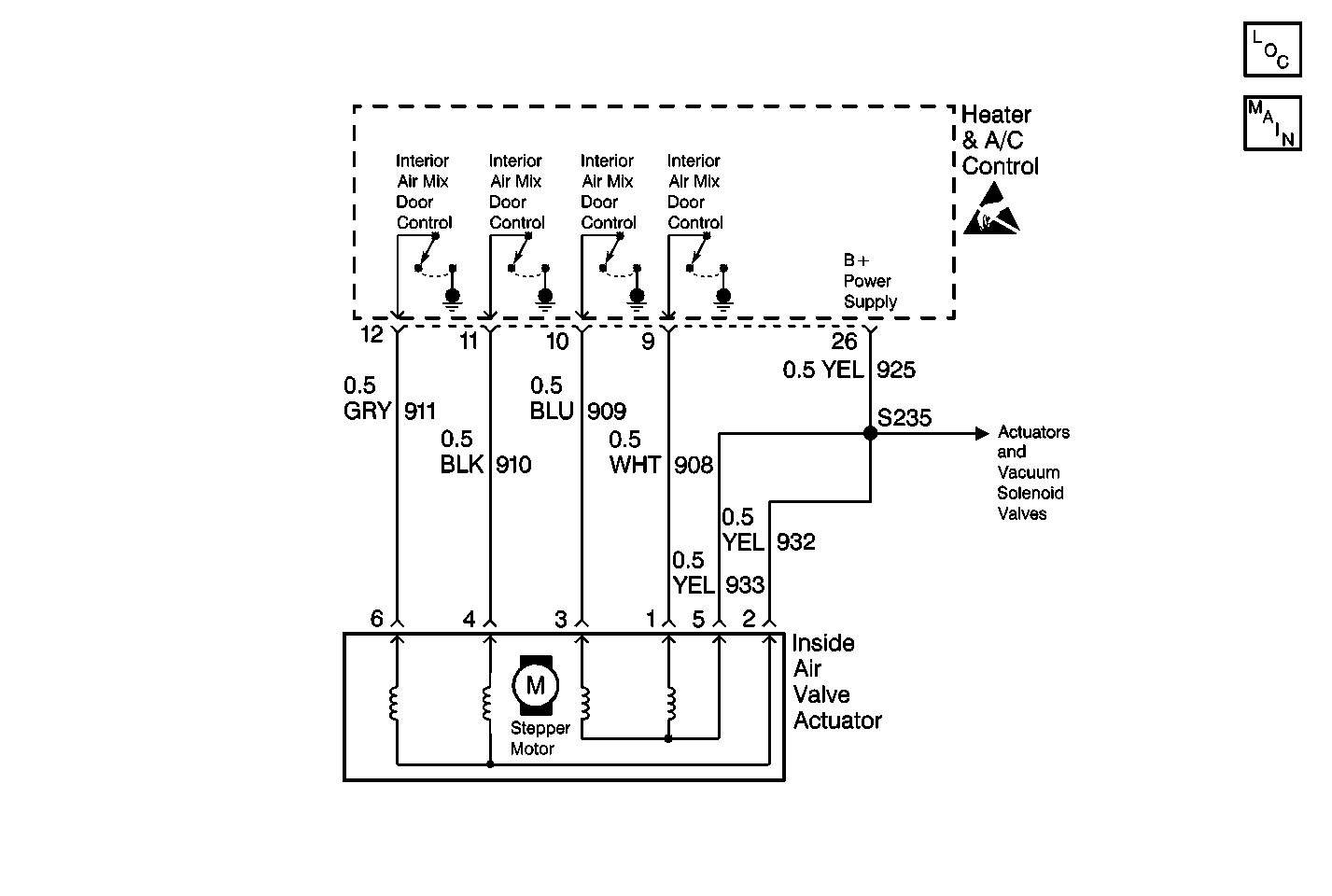
Circuit Description
The inside air valve actuator is a DC stepper motor by design. The stepper motor has four field windings that are controlled by the heater and A/C control. When the heater and A/C control needs to move the stepper motor, it energizes the proper field windings which rotates the armature a fixed amount in the proper direction. This fixed amount is called a step. Battery voltage for the stepper motor is supplied by the heater and A/C control when the ignition is in the ON position.
Attached to the stepper motor is a small gear. When the stepper motor is installed on the HVAC module, it meshes with a larger gear which is part of an assembly that drives the linkage of the air mix door.
Conditions for Setting the DTC
When the ignition is in the ON position, the heater and A/C control measures the current of all four coil wires of the stepper motor . The measured current is averaged by the controller and a "fail threshold" is calculated. After the output current is measured it is compared with the threshold value. If the current is too low then the output from the controller to the stepper motor is presumed to be open or shorted to ground. This step is repeated 3 times within a 10 second time frame.
Action Taken When the DTC Sets
| • | Stores a DTC 16 in the heater and A/C control memory. |
| • | The fault detection process is repeated 3 times at a fixed interval of 70 ms to allow for debouncing. |
| When the fault is set, the stepper motor can no longer be controlled. |
Conditions for Clearing the DTC
| • | The conditions for the fault are no longer present. |
| • | Using a scan tool. |
| • | A history DTC will clear after 20 consecutive ignition cycles if the conditions for the fault is no present. |
Diagnostic Aids
| • | If the DTC is a history or an intermittent. Try performing the tests shown while moving the harness wiring and connectors, this can often cause the malfunction to appear. |
| • | Visually inspect stepper motor connector and harness for damage, corrosion or water intrusion. |
| • | Check for adequate terminal tension, mis-routed harness, rubbed through wire insulation, and broken wire inside the insulation. |
Test Description
The numbers below refer to the step numbers on the diagnostic table.
-
Checks the operation of the actuators to see if they are capable of moving when commanded.
-
Determines if an open circuit exists between the heater and A/C control and actuator.
Step | Action | Value(s) | Yes | No |
|---|---|---|---|---|
1 | Did you perform the HVAC Systems Diagnostic System Check? | -- | Go to Diagnostic System Check | |
NOTE: Until the stepper motor reaches the commanded position the status of this parameter changes from INACTIVE to ACTIVE. Does the scan tool display ACTIVE for the motor and 70% to 100% for the position? | -- | |||
3 | Repeat the above steps but press the DEFROST button. Does the scan tool display ACTIVE for the motor and 0% for the position? | -- | Go to Diagnostic Aids | |
Does each circuit have continuity? | -- | |||
5 | Check each circuit for a short to ground. Are the resistance readings within the specified range? | OL | ||
6 | Locate and repair the open in the circuits that failed the test. Is the repair complete? | -- | -- | |
7 | Replace the interior air valve actuator. Did you complete the replacement? | -- | -- | |
8 | Locate and repair the short to ground in the circuit(s) that failed the test. Is the repair complete? | -- | -- | |
9 |
Is a current DTC 16 present? | -- | System OK | |
10 | Replace and program the heater and A/C control. Is the replacement and programming complete? | -- | System OK | -- |
