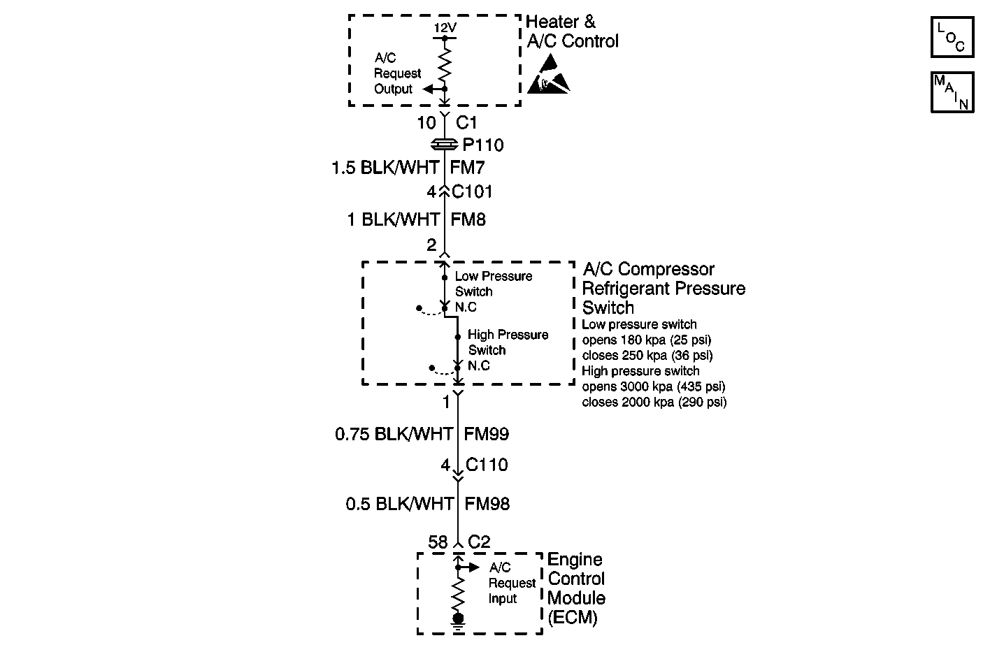
Circuit Description
When the A/C button is pressed ON, battery voltage is supplied to terminal 2 of the A/C compressor refrigerant pressure switch. The A/C pressure switch is closed when the pressure in the refrigerant line is approximately 180 KPa (36 psi). With the pressure switch closed, battery voltage is supplied to terminal 58 connector C2 of the Engine Control Module (ECM). After receiving the A/C request input, the ECM grounds the A/C compressor relay coil which energizes the relay closing the relay contacts. With the relay contacts closed, the circuit is completed allowing battery voltage to be applied to the A/C compressor clutch coil. The A/C compressor clutch coil energizes and the compressor clutch will now engage.
The heater and A/C control monitors the state of the compressor clutch relay through the A/C cutout input circuit.
Conditions for Running the DTC
| • | The ignition is ON. |
| • | The A/C request is inactive (A/C OFF). |
Conditions for Setting the DTC
The heater and A/C control detects an open or short to voltage in the A/C request circuit.
Action Taken When the DTC Sets
| • | Stores a DTC 35 in the heater and A/C control memory. |
| • | The heater and A/C control does not disable the output. |
Conditions for Clearing the DTC
| • | The condition for the fault is no longer present. |
| • | Using a scan tool. |
| • | A history DTC will clear after 20 consecutive ignition cycles if the condition for the fault is no longer present. |
Diagnostic Aids
| • | If the DTC is a history or an intermittent. Try to perform the test shown while moving the wiring harnesses and connectors, this often can cause the malfunction to appear. |
| • | When moving related harnesses and harness connectors, visually/physically inspect wiring and connectors for the following: |
| - | Dirt or corrosion on the terminals. The terminals must be clean and free of any foreign material which could impede proper terminal contact. |
| - | Damaged connector body, exposing the terminals to moisture and dirt, as well as not maintaining proper terminal orientation with the component or mating connector. |
| - | Wire insulation which is rubbed through, causing an intermittent short as the bare area touches other wiring or parts of the vehicle. |
| • | Test the power and ground circuits before replacing the heater and A/C control. |
Test Description
The number(s) below refer to the step number(s) on the diagnostic table.
-
This step determines if the malfunction is present.
-
This step verifies that the A/C request circuits and the A/C compressor refrigerant pressure switch are not open.
-
This step tests for open contacts in the A/C compressor refrigerant pressure switch.
-
This step tests for a short to voltage in the A/C request circuits. The voltage measurement at the ECM should drop from 12 volts to 6.5 volts when the A/C request is commanded from active to inactive.
-
This step verifies that the A/C compressor refrigerant switch is not internally shorted to voltage.
Step | Action | Value(s) | Yes | No |
|---|---|---|---|---|
1 | Did you perform the HVAC Systems Diagnostic System Check? | -- | Go to Diagnostic System Check | |
Does the AC-CUTOUT parameter change state? | -- | Go to Diagnostic Aids | ||
Does the voltage measure near the specified value? | 12 V | |||
Does the voltage measure near the specified value? | 12 V | |||
5 | Test both the A/C request output circuit of the heater and A/C control and the A/C request input circuit of the ECM for an open or a high resistance. Did you find and correct the condition? | -- | ||
Does the voltage measure near the specified value? | 6.5 V | |||
Does the voltage measure near the specified value? | 6.5 V | |||
8 | Test both the A/C request output circuit of the heater and A/C control and the A/C request input circuit of the ECM for short to voltage. Did you find and correct the condition? | -- | ||
9 | Inspect for poor connections at the harness connector of the A/C compressor refrigerant pressure switch. Refer to Testing for Intermittent Conditions and Poor Connections and Connector Repairs in Wiring Systems. Did you find and correct the condition? | -- | ||
10 | Inspect for poor connections at the harness connector of the heater and A/C control. Refer to Testing for Intermittent Conditions and Poor Connections and Connector Repairs in Wiring Systems. Did you find and correct the condition? | -- | ||
11 | Inspect for poor connections at the harness connector of the EMC. Refer to Testing for Intermittent Conditions and Poor Connections and Connector Repairs in Wiring Systems. Did you find and correct the condition? | -- | ||
12 | Replace the A/C compressor refrigerant pressure switch. Did you complete the replacement? | -- | -- | |
13 | Replace the heater and A/C control. Did you complete the replacement? | -- | -- | |
14 | Replace the ECM. Did you complete the replacement? | -- | -- | |
15 |
Does the DTC reset? | -- | System OK |
