For 1990-2009 cars only
SMU - Revised Cooling Fan and Motor Replacement - Auxiliary Procedure

| Subject: | Revised Cooling Fan and Motor Replacement - Auxiliary Procedure |
| Models: | 2000-2001 Cadillac Catera |
This bulletin is being issued to revise the Cooling Fan and Motor Replacement - Auxiliary repair procedure in the Engine Cooling sub-section of the Service Manual. Please replace the current information in the Service Manual with the following information.
The following information has been updated in SI2000. If you are using a paper version of this Service Manual, please make a reference to this bulletin on the affected page.
Removal Procedure
- Disconnect the negative battery cable. Refer to Battery Negative Cable Disconnect/Connect Procedure in Engine Electrical.
- Remove the impact bar. Refer to Impact Bar Replacement - Front Bumper in Bumpers.
- Remove the fresh air intake duct screws.
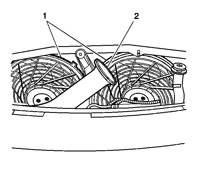
- Remove the fresh air intake duct (2) from the air cleaner assembly.
- Remove the auxiliary cooling fan shroud (1).
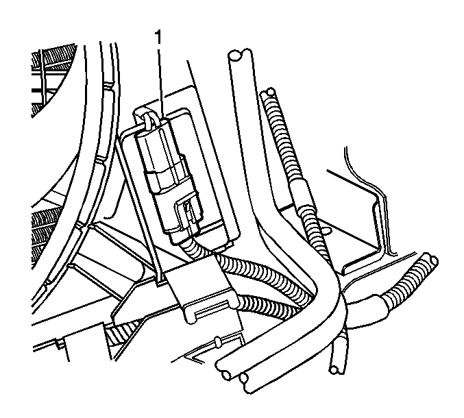
- Disconnect the auxiliary cooling fan electrical connector (1).
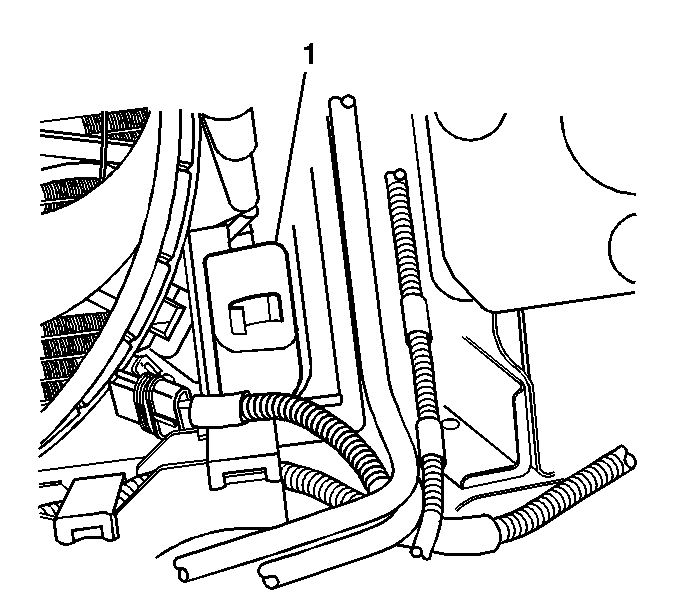
- Remove the electrical connector access cover (1) from the fan shroud.
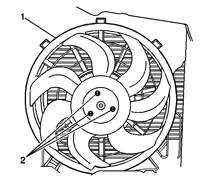
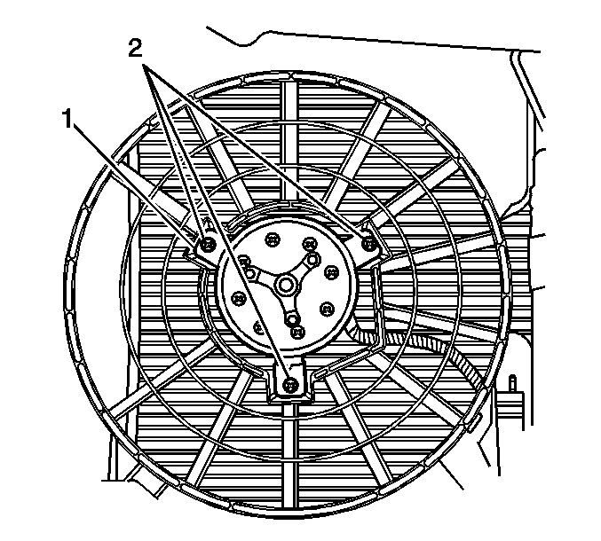
- Remove the auxiliary cooling fan blade screws (2).
- Remove the auxiliary cooling fan blade (1) from the fan motor.
- Remove the auxiliary cooling fan motor bolts (2).
- Remove the auxiliary cooling fan motor (1).
Installation Procedure
- Install the auxiliary cooling fan motor (1).
- Install the auxiliary cooling fan motor bolts (2).
- Install the auxiliary cooling fan blade (1) to the fan motor.
- Install the auxiliary cooling fan blade screws (2).
- Install the electrical connector access cover (1) to the fan shroud.
- Connect the auxiliary cooling fan electrical connector (1).
- Install the auxiliary cooling fan shroud (1).
- Install the fresh air intake duct (2) to the air cleaner assembly.
- Install the fresh air intake duct screws.
- Install the impact bar. Refer to Impact Bar Replacement - Front Bumper in Bumpers.
- Connect the negative battery cable. Refer to Battery Negative Cable Disconnect/Connect in Engine Electrical.

Tighten
Tighten the bolts to 4 N·m (35 lb in).

Notice: Refer to Fastener Notice in Cautions and Notices.
Tighten
Tighten the screws to 4 N·m (35 lb in).


Tighten
Tighten the screw to 4 N·m (35 lb in).
