Knock Sensor Replacement Bank 1
Removal Procedure
- Disconnect the knock sensor from the wiring harness.
- Remove the generator and the drive belt tensioner. Refer to Generator Replacement in Engine Electrical.
- Remove the knock sensor pigtail from the retaining clips on the rear timing belt cover.
- Remove the bolt in the center of the knock sensor.
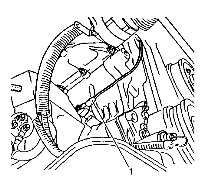
- Remove the knock sensor (1) from the engine block.
Important: The knock sensor pigtail is guided past the rear timing belt cover by several retaining clips. Only one retainer clip is shown. Note the positioning of the knock sensor pigtail.

Installation Procedure
- Thoroughly clean the mating surfaces of the knock sensor and the engine block. The entire contact surface of the knock sensor must lie directly on the engine block.
- Install the knock sensor (1) on to the engine block.
- Install the knock sensor pigtail into the retaining clips. Ensure that the pigtail does not contact any moving parts.
- Install the generator and the drive belt tensioner. Refer to Generator Replacement in Engine Electrical.
- Connect the knock sensor connector.

Notice: Use the correct fastener in the correct location. Replacement fasteners must be the correct part number for that application. Fasteners requiring replacement or fasteners requiring the use of thread locking compound or sealant are identified in the service procedure. Do not use paints, lubricants, or corrosion inhibitors on fasteners or fastener joint surfaces unless specified. These coatings affect fastener torque and joint clamping force and may damage the fastener. Use the correct tightening sequence and specifications when installing fasteners in order to avoid damage to parts and systems.
Important: Do not use washers, spring washers, or toothed washers when installing the knock sensor. Tighten all of the fasteners to the proper torque.
Tighten
Tighten the sensor to 20 N·m (15 lb ft).
Important: The knock sensor pigtail is guided past the rear timing belt cover by several retaining clips. Only one retainer clip is shown. Install the knock sensor pigtail as noted during removal.
Knock Sensor Replacement Bank 2
Removal Procedure
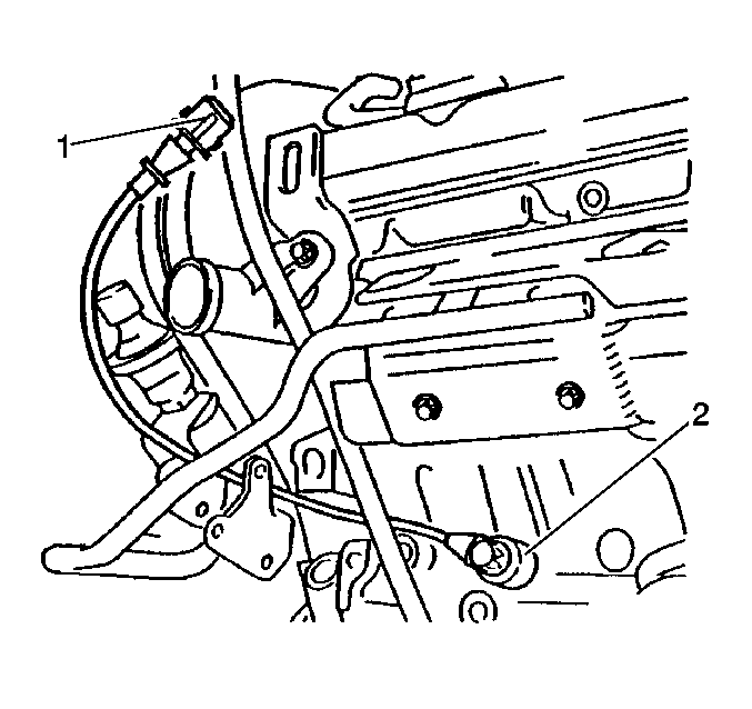
- Disconnect the knock sensor connector (1).
- Remove the power steering pump pulley. Refer to Power Steering Pump Pulley Replacement in Power Steering System.
- Remove the knock sensor pigtail from the retaining clips.
- Securely attach a scrap piece of wire about 36 inches long to the knock sensor pigtail. Later, this will be used as a pull wire to guide the new sensor pigtail back through the same routing.
- Remove the left hand engine mount. Refer to Engine Mount Replacement in Engine Mechanical.
- Remove the fastening bolts for the engine mount bracket and remove the bracket from the block.
- Remove the bolt from the center of the knock sensor.
- Gently pull the knock sensor pigtail through the wiring conduit and out. Stop when the pull wire is free of the conduit at both ends.
- Detach the knock sensor from the pull wire, leaving the pull wire in place.

Important: Observe the routing of the pigtail for proper installation.
Installation Procedure
- Thoroughly clean the mating surfaces of the knock sensor and the engine block. The entire contact surface of the knock sensor must lie directly on the engine block.
- Install the knock sensor (2) to the engine block.
- Securely fasten the knock sensor pigtail to the pull wire that was left in place during the removal procedure.
- Use the pull wire in order to guide the knock sensor pigtail back through the proper route, out to the retaining clip at the power steering pump.
- Remove the pull wire.
- Connect the wiring harness (1) to the knock sensor.
- Fasten the pigtail to the retaining clips.
- Install the engine mount bracket to the engine block and install the bolts.
- Install the left hand engine mount. Refer to Engine Mount Replacement in Engine Mechanical.
- Install the power steering pump pulley. Refer to Power Steering Pump Pulley Replacement in Power Steering System.

Notice: Use the correct fastener in the correct location. Replacement fasteners must be the correct part number for that application. Fasteners requiring replacement or fasteners requiring the use of thread locking compound or sealant are identified in the service procedure. Do not use paints, lubricants, or corrosion inhibitors on fasteners or fastener joint surfaces unless specified. These coatings affect fastener torque and joint clamping force and may damage the fastener. Use the correct tightening sequence and specifications when installing fasteners in order to avoid damage to parts and systems.
Important: Do not use any washers, any spring washers, or any toothed washers when installing the knock sensor. Tighten all of the fasteners to the proper torque.
Tighten
Tighten the sensor to 20 N·m (15 lb ft).
Important: When routing the pigtail for the knock sensor, ensure that the pigtail does not contact the exhaust manifold or any moving parts and is correctly routed.
Tighten
Tighten the bolts to 60 N·m (44 lb ft).
