Flange Removal Procedure
Tools Required
J 42066 Wheel Bearing
Hub Flange Holding Tool
- Raise and support the vehicle. Refer to
Lifting and Jacking the Vehicle
in General Information.
- Remove the propeller shaft. Refer to
Two-Piece Propeller Shaft Replacement
.
- Remove the propeller shaft coupling.

- The flange run-out is
minimized and the pinion bearing preload is maintained by reassembling in
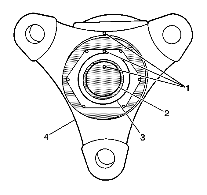
the original position. Lightly match-mark (1) the following as an
aid for reassembly:
| • | On the differential drive pinion flange nut (3). |
| • | On the differential drive pinion flange (4). |
| • | On the differential drive pinion gear end (2). |
- Install the J 42066
onto the differential drive pinion flange.
- Use the J 42066
to hold the differential drive pinion flange.
- Remove the differential drive pinion flange nut.
- Remove the J 42066
.
- Install a universal gear puller to the pinion flange.
- Remove the pinion flange from the differential drive pinion gear.
Seal Removal Procedure
- Remove the drive pinion flange.

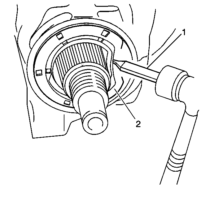
- Use a drift (1)
and use a deadblow hammer to remove the differential drive pinion oil seal (2)
from the differential housing.
Important: Position the drift on an angle to drive the seal inward away from the
housing surface to prevent affecting the surface condition of the housing.
Take care not to damage the differential housing as this could result in a
leak after reassembly.
Seal Installation Procedure
Tools Required
J 42108 Pinion Seal
Driver

- Lubricate the lip of the
new seal with rear axle lubricant.
- Lightly coat the outside of the new seal with a non-hardening
gasket cement.
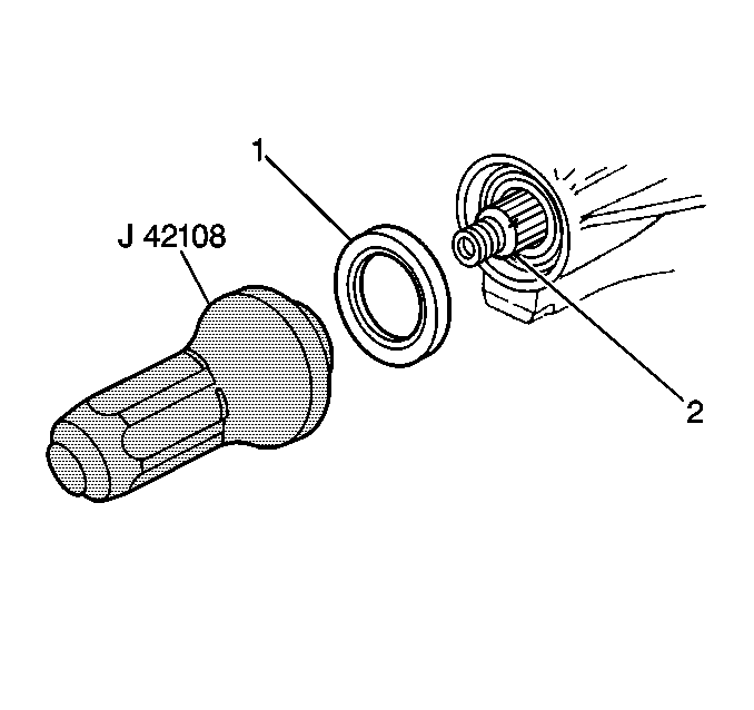
- Use the J 42108
to drive the seal (1) over the pinion gear (2) squarely into
the differential housing.
Flange Installation Procedure
Tools Required
J 42066 Wheel Bearing
Hub Flange Holding Tool
- Ensure that the drive pinion gear shaft threads are free from
burrs.
- Coat the splines with the rear axle lubricant.
- Coat the surface of the pinion flange with rear axle lubricant.
- Install the differential drive pinion flange onto the differential
drive pinion gear.
Important: The pinion flange has an interference fit on the pinion gear shaft splines.
The pinion flange should only be pulled into place by tightening the retaining
nut. Do NOT use force or hammer the flange during the installation of the
drive pinion flange onto the drive pinion.
Install the differential drive pinion flange nut.
Tighten
Gradually tighten the flange nut until the pinion shaft end play is
reduced to approximately 0.50 mm (0.020 in).

- If REUSING the drive pinion
flange continue tightening the nut while alternatively turning the pinion
gear to seat the bearings until the alignment marks (1) align. Then,
further tighten the nut no more than an additional 5 degrees. Backing
off the pinion flange nut to compensate for overtightening the nut will not
properly set preload.

- If a NEW drive pinion
flange is installed, the differential must be removed to set the drive pinion
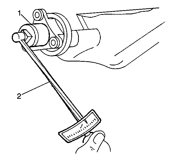
bearing preload. Set the preload without the carrier installed and with the
bearings lubricated to 1.0-1.7 N·m (9-15 lb in)
on the new bearings or 0.9-1.2 N·m (8-11 lb in)
with used bearings.
| • | The preload specifications are being approached when no further
end play is detectable and when the holder will no longer pivot freely as
the differential drive pinion gear is rotated. |
| • | Do NOT attempt further tightening until you have tested the preload. |
| • | Carefully perform the final tightening only after you have tested
the preload. |
| • | Minute tightening of the nut adds significant pound inches of
turning torque. |
| • | Further tighten the nut slightly while testing the preload after
each tightening. |
| • | Exceeding the preload specifications compresses the collapsible
spacer too far, thus requiring the installation of a new spacer. |
- Install the propeller shaft coupling.
- Install the propeller shaft. Refer to
Two-Piece Propeller Shaft Replacement
.
- Fill and inspect the lubricant level. Refer to
Lubricant Level Check
.
- Lower the vehicle.


