| Table 1: | Door Lock Switch |
| Table 2: | Horn Relay K63 |
| Table 3: | Ignition Switch and Lifting Magnet |
| Table 4: | LH Front Side Door Jamb Switch |
| Table 5: | LH Front Side Door Lock Switch |
| Table 6: | LH Rear Side Door Jamb Switch |
| Table 7: | Low Beam Relay K131 |
| Table 8: | Park Lamp Relay K130 |
| Table 9: | Remote Control Door Lock Receiver (RCDLR) |
| Table 10: | RH Front Side Door Jamb Switch |
| Table 11: | RH Front Side Door Lock Switch |
| Table 12: | RH Rear Side Door Jamb Switch |
| Table 13: | Theft Deterrent Module Connector |
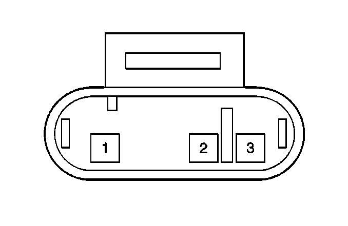
| |||
|---|---|---|---|
Connector Part Information | 0688030101 | ||
Pin | Wire Color | Circuit No. | Function |
1 | BLK | F4 | Ground to G200 |
2 | BRN/PPL | XY810 | Door Open Signal Input |
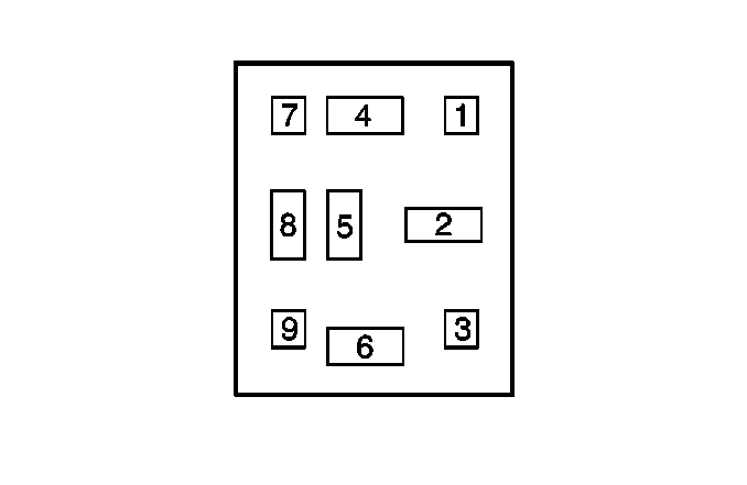
| |||
|---|---|---|---|
Connector Part Information | ZF 9-14 | ||
Pin | Wire Color | Circuit No. | Function |
1 | -- | -- | Not Used |
2 | RED | A121 | B+ from Fuse #8 |
3 | -- | -- | Not Used |
4 | BRN/WHT | XM30 | Horn ON Signal |
5 | -- | -- | Not Used |
6 | BRN/WHT | XM1 XM899 | Switch Signal |
7 | -- | -- | Not Used |
8 | BLK | F700 | Ground to G103 |
9 | -- | -- | Not Used |
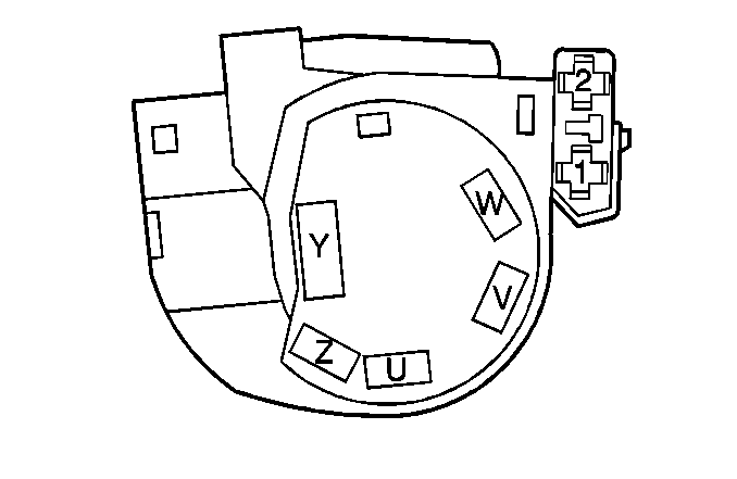
| |||
|---|---|---|---|
Connector Part Information | ZF6-5 | ||
Pin | Wire Color | Circuit No. | Function |
1 | RED | A905 | B+ from Fuse #24 |
2 | GRN | U900 | Brake to Shift Signal |
U | BRN | X826 | B+ in the ON Position |
V | BRN | X1 | B+ in the ON or START Position |
W | RED | A19 | B+ when the Key is Inserted |
Y | RED | A503 | B+ from Fuse V2 |
Z | BLK/RED | FA700 | Starter Solenoid Signal |
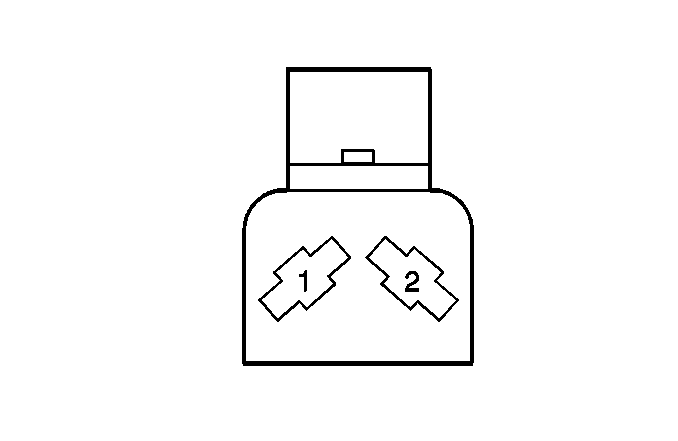
| |||
|---|---|---|---|
Connector Part Information | F 2-42 | ||
Pin | Wire Color | Circuit No. | Function |
1 | GRY/WHT | RM2 | Door Open Signal |
2 | GRY | R2 | Door Open Signal |
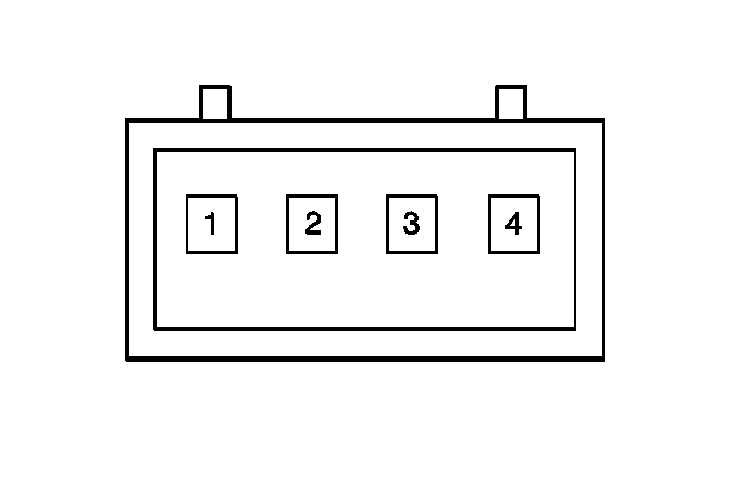
| |||
|---|---|---|---|
Connector Part Information | F 4-21 | ||
Pin | Wire Color | Circuit No. | Function |
1 | BLK/BRN | FX805 | Door Lock Signal |
2 | BLK/PPL | FY805 | Door Unlock Signal |
3 | RED/BLU | AP807 | Illumination Signal |
4 | BLK | F12 | Ground to G200 |

| |||
|---|---|---|---|
Connector Part Information | F 2-42 | ||
Pin | Wire Color | Circuit No. | Function |
1 | GRY | R2 | Door Open Signal |
2 | GRY | R1 | Door Open Signal |
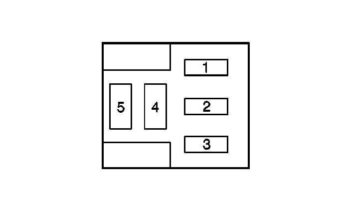
| |||
|---|---|---|---|
Connector Part Information | ZFW 5-20 | ||
Pin | Wire Color | Circuit No. | Function |
1 | BRN/RED | XA810 XA811 | Relay Control |
2 | -- | -- | Not Used |
3 | AM811 | AM811 | Exterior Lamp Power |
4 | YEL | B50 | Lamps ON Signal |
5 | RED | A814 | B+ from Fuse V3 |

| |||
|---|---|---|---|
Connector Part Information | ZFW 5-20 | ||
Pin | Wire Color | Circuit No. | Function |
1 | BRN/WHT | XM810 XM815 | Relay Control |
2 | -- | -- | Not Used |
3 | RED/WHT | AM810 AM811 | Exterior Lamp Power |
4 | GRY/GRN | RU812 | Lamp ON Signal |
5 | RED | A813 | B+ from Fuse V3 |
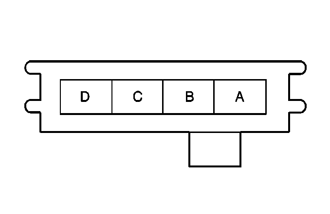
| |||||||
|---|---|---|---|---|---|---|---|
Connector Part Information |
| ||||||
Pin | Wire Color | Circuit No. | Function | ||||
A | RED | A823 | B+ from Fuse #28 | ||||
B | BRN/WHT | XM832 | Class 2 Serial Data | ||||
C | BLK/RED | F802 | Ground to G103 | ||||
D | -- | -- | Not Used | ||||

| |||
|---|---|---|---|
Connector Part Information | F 2-42 | ||
Pin | Wire Color | Circuit No. | Function |
1 | -- | -- | Not Used |
2 | GRY | R6 | Door Open Signal |

| |||
|---|---|---|---|
Connector Part Information | F 4-21 | ||
Pin | Wire Color | Circuit No. | Function |
1 | BLK/BRN | FX805 | Door Lock Signal |
2 | BLK/PPL | FY805 | Door Unlock Signal |
3 | RED/BLU | AP807 | Illumination Signal |
4 | BLK | F12 | Ground to G200 |

| |||
|---|---|---|---|
Connector Part Information | F 2-42 | ||
Pin | Wire Color | Circuit No. | Function |
1 | GRY | R2 | Door Open Signal |
2 | GRY | R1 | Door Open Signal |
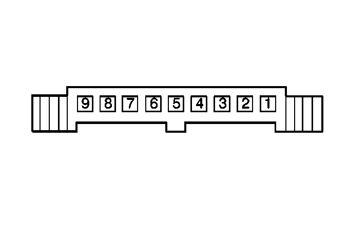
| |||
|---|---|---|---|
Connector Part Information | F 9-33 | ||
Pin | Wire Color | Circuit No. | Function |
1 | -- | -- | Not Used |
2 | BRN/BLU | XP21 | Theft Deterrent Request Signal |
3 | -- | -- | Not Used |
4 | BLK | F150 | Ground |
5 | BRN | X5 | Ignition Switch Input Signal |
6 | BLU/RED | PA13 | Vehicle Speed Signal |
7 | BLU/RED | PA14 | Theft Deterrent Output Signal |
8 | BRN/WHT | XM15 | Serial Data |
9 | RED | A17 | Battery Input |
