Camshaft Cover Replacement Right
Removal Procedure
- Remove the intake plenum. Refer to Intake Plenum Replacement .
- Remove the intake manifold. Refer to Intake Manifold Replacement .
- Remove the coil pack. Refer to Ignition Coil Replacement in Engine Electrical.
- Remove the knock sensor wire harness nut and bracket.
- Remove the camshaft cover bolts.
- Remove the camshaft cover.
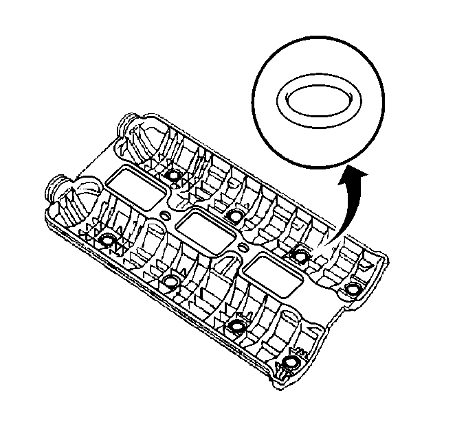
- Remove the camshaft cover seals.
- Clean the camshaft cover.
- Clean the sealing surfaces.

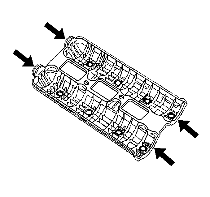
Important: Ensure all eight sealing O-rings are accounted for. The O-rings may stick to the camshaft bearing caps or they may fall into the oil return journals in the cylinder head.
Installation Procedure
- Lightly coat new seals, including the O-rings, with engine oil prior to installation to assist in holding the O-ring seals to the camshaft cover.
- Install the camshaft cover seals.
- Apply a thin coat of silicone sealer GM P/N 12345997 at the front and at the back of the seals.
- Install the camshaft cover to the cylinder head.
- Install the camshaft cover bolts.
- Install the knock sensor wire harness bracket and nut.
- Install the coil pack. Refer to Ignition Coil Replacement in Engine Electrical.
- Install the intake manifold. Refer to Intake Manifold Replacement .
- Install the intake plenum. Refer to Intake Plenum Replacement .
- Connect the battery negative cable. Refer to Battery Negative Cable Disconnection and Connection in Engine Electrical.

Notice: Use the correct fastener in the correct location. Replacement fasteners must be the correct part number for that application. Fasteners requiring replacement or fasteners requiring the use of thread locking compound or sealant are identified in the service procedure. Do not use paints, lubricants, or corrosion inhibitors on fasteners or fastener joint surfaces unless specified. These coatings affect fastener torque and joint clamping force and may damage the fastener. Use the correct tightening sequence and specifications when installing fasteners in order to avoid damage to parts and systems.
Tighten
Tighten the camshaft cover bolts to 8 N·m (71 lb in).
Tighten
Tighten the knock sensor wire harness bracket nut until fully seated
and not stripped.
Camshaft Cover Replacement Left
Removal Procedure
- Remove the intake plenum. Refer to Intake Plenum Replacement .
- Remove the intake manifold. Refer to Intake Manifold Replacement .
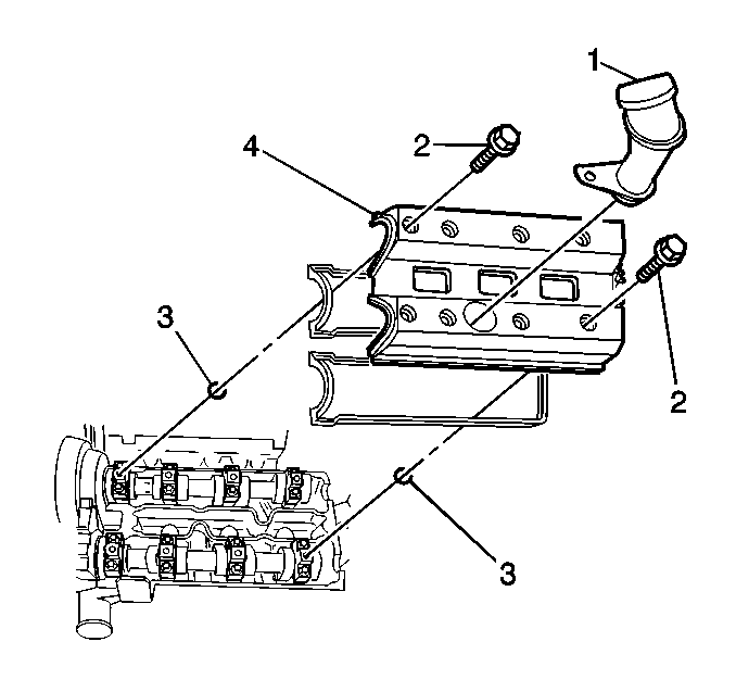
- Remove the oil filler spout (1) by unlocking the tab and twisting counterclockwise.
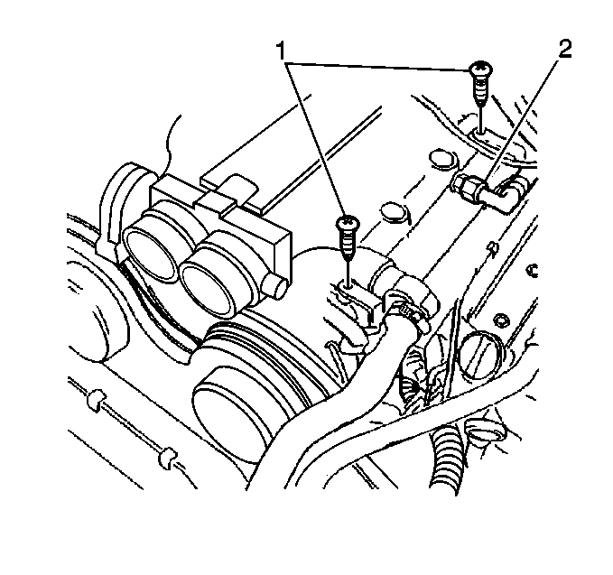
- Remove the wiring harness channel bolts (1) and position the wiring harness channel out of the way.
- Disconnect the Camshaft Position Sensor (CMP) electrical connection and cut the plastic tie.
- Remove the coil pack. Refer to Ignition Coil Replacement in Engine Electrical.
- Remove the camshaft cover bolts.
- Remove the camshaft cover.
- Remove the camshaft cover seals.
- Clean the camshaft cover.
- Clean the sealing surfaces.


Important: Ensure all eight sealing O-rings are accounted for. The O-rings may stick to the camshaft bearing caps or they may fall into the oil return journals in the cylinder head.
Installation Procedure
- Lightly coat the new seals, including the O-rings, with engine oil prior to installation to assist in holding the O-ring seals to the camshaft cover.
- Install the camshaft cover seals.
- Apply a thin coat of silicone sealer GM P/N 12345997 at the front and at the back of the seals.
- Install the camshaft cover to the cylinder head.
- Install the camshaft cover bolts.
- Install the coil pack. Refer to Ignition Coil Replacement in Engine Electrical.
- Connect the CMP electrical connection and secure the wire with a plastic tie.
- Reposition the wiring harness channel and install the bolts (1).
- Install the oil filler spout (1) by twisting clockwise and snapping in place.
- Install the intake manifold. Refer to Intake Manifold Replacement .
- Install the intake plenum. Refer to Intake Plenum Replacement .


Notice: Use the correct fastener in the correct location. Replacement fasteners must be the correct part number for that application. Fasteners requiring replacement or fasteners requiring the use of thread locking compound or sealant are identified in the service procedure. Do not use paints, lubricants, or corrosion inhibitors on fasteners or fastener joint surfaces unless specified. These coatings affect fastener torque and joint clamping force and may damage the fastener. Use the correct tightening sequence and specifications when installing fasteners in order to avoid damage to parts and systems.
Tighten
Tighten the camshaft cover bolts to 8 N·m (71 lb in).

Tighten
Tighten the wiring harness channel bolts to 8 N·m (71 lb in).

