Tools Required
J 35268-A Camshaft Seal Installer
- Install the camshafts to the cylinder head:
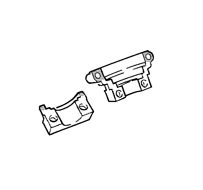
- Apply a small amount of Loctite® 518, or equivalent, on the forward edge of the front bearing caps ONLY to ensure an adequate seal between the bearing cap and the cylinder head.
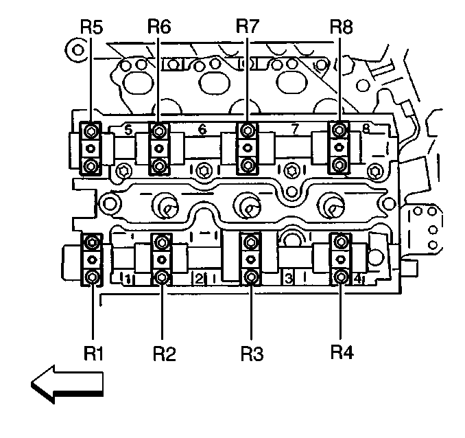
- Install the bearing caps for the RH side cylinder head.
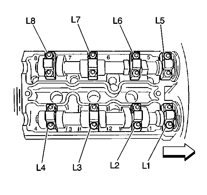
- Install the bearing caps for the LH side cylinder head.
- Install the camshaft bearing cap bolts.
- Coat the lip of the camshaft seal with a small amount of GM P/N 12377985, chassis grease or equivalent, to aid in installation.
- Use the J 35268-A to tap the camshaft seal into place.
Important:
• The intake is marked with blue paint between bearings 2 &
3 and has a code G or B cast into it near the number one bearing surface. • The exhaust is marked with green paint between bearings 2 &
3 and has a code A cast into it near the number one bearing surface.

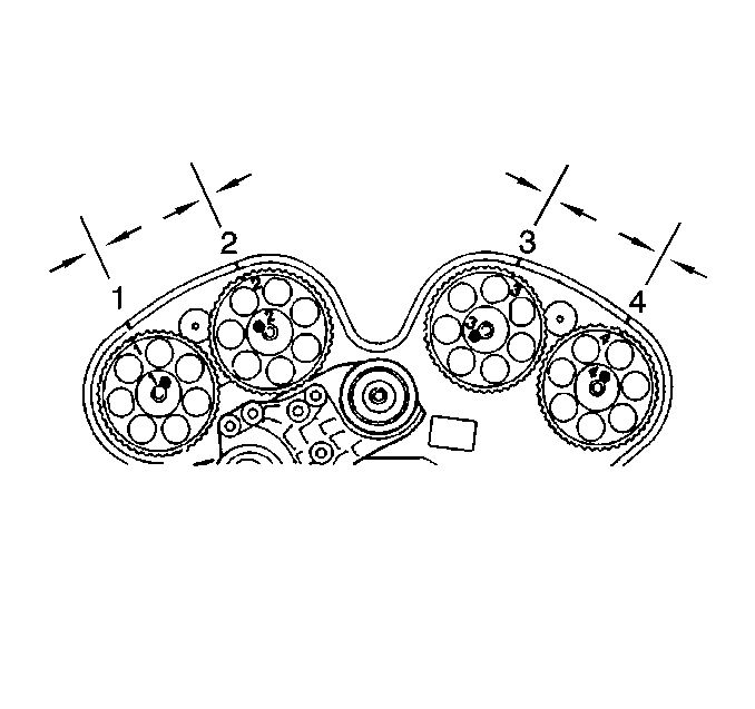
| 1.1. | Ensure the sprocket pin on the RH exhaust camshaft is approximately in the 1 o'clock position. |
| 1.2. | Ensure the sprocket pin on the RH intake camshaft is approximately in the 11 o'clock position |
| 1.3. | Ensure the sprocket pin on the LH exhaust camshaft is approximately in the 12 o'clock position. |
| 1.4. | Ensure the sprocket pin on the LH intake camshaft is approximately in the 7 o'clock position. |

Important: DO NOT allow the sealer to get into the oil journal of the cap.

The bearing caps for the RH side are marked with an L1, L2, L3, etc. followed by a number.

The bearing caps for the LH side are marked with an R1, R2, R3, etc. followed by a number
Tighten
Tighten the camshaft bearing cap bolts evenly, starting from the center
cap moving outward to 8 N·m (71 lb in).
Ensure the camshaft seal is fully and evenly seated.
