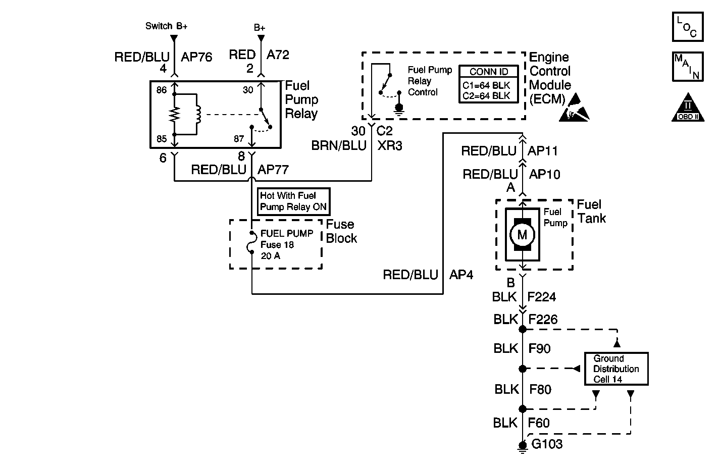
Circuit Description
The fuel pump relay coil is powered by switched battery voltage from the engine controls power relay. The engine control module (ECM) controls the relay by grounding the control circuit using an internal solid state device called a driver. When the ECM detects reference pulses from the crankshaft position (CKP) sensor, the ECM will enable the fuel pump. The switch side of the relay is connected directly to battery positive voltage. The relay controls the power to the fuel pump fuse and the fuel pump.
Diagnostic Aids
Use the J 35616 connector test adapter kit for any test that requires probing the ECM harness connector or a component harness connector.
If the fuel pump continues to run with the ignition ON and the engine OFF, test the fuel pump relay control circuit for a short to ground.
Ensure that the CKP sensor is functioning properly. The fuel pump relay will not turn ON if it is not receiving CKP reference pulses.
Test Description
The numbers below refer to the step numbers on the diagnostic table.
-
Do not use this table unless you were sent here from other diagnostic service information. There are important steps that must be performed prior to using this diagnostic table.
-
This step checks for DTC P0230. DTC P0230 will detect any circuit faults on the fuel pump relay control circuit.
-
The fuel pump jumper harness connector is accessible without lowering the fuel tank. The fuel pump circuits can be tested for operation up to this point of the vehicle harness.
-
Proper fuel pump circuit operation has been observed up to the fuel pump jumper harness. The fuel tank will have to be lowered in order to continue testing.
Step | Action | Values | Yes | No | ||||
|---|---|---|---|---|---|---|---|---|
Did you perform the Powertrain On-Board Diagnostic (OBD) System Check? | -- | Go to Step 2 | ||||||
Is DTC P0230 set? | -- | Go to Step 3 | ||||||
3 | Use the test lamp connected to a ground and probe terminal 2 of the relay harness. Does the test lamp illuminate? | -- | Go to Step 4 | Go to Step 12 | ||||
4 |
Does the test lamp turn ON and OFF when commanded? | -- | Go to Step 5 | Go to Step 14 | ||||
5 | Inspect the fuel pump fuse. Is the fuse blown? | -- | Go to Step 11 | Go to Step 6 | ||||
6 |
Does the test lamp illuminate at both fuse test points? | -- | Go to Step 7 | Go to Step 12 | ||||
Does the test lamp illuminate? | -- | Go to Step 8 | Go to Step 12 | |||||
8 |
Does the test lamp illuminate? | -- | Go to Step 9 | Go to Step 13 | ||||
Was a connection or wiring repair made? | -- | Go to Step 16 | Go to Step 10 | |||||
10 |
Is proper fuel pump operation observed? | -- | Go to Step 16 | Go to Step 15 | ||||
11 | Locate and repair the cause of the blown fuel pump fuse. Possible causes include a shorted to ground fuel pump B+ circuit between the fuel pump fuse and the fuel pump or an internally shorted fuel pump. Refer to Wiring Repairs in Wiring Systems. Is the action complete? | -- | Go to Step 16 | -- | ||||
12 | Repair the open in the fuel pump B+ circuit. Refer to Wiring Repairs in Wiring Systems. Is the action complete? | -- | Go to Step 16 | -- | ||||
13 | Repair the open in the fuel pump ground circuit. Refer to Wiring Repairs in Wiring Systems. Is the action complete? | -- | Go to Step 16 | -- | ||||
14 | Replace the fuel pump relay. Is the action complete? | -- | Go to Step 16 | -- | ||||
15 | Replace the fuel pump. Refer to Fuel Pump Replacement . Is the action complete? | -- | Go to Step 16 | -- | ||||
16 |
Does the engine start and continue to run? | -- | Go to Step 17 | |||||
17 |
Are any DTCs displayed? | -- | Go to the applicable DTC table | System OK |
