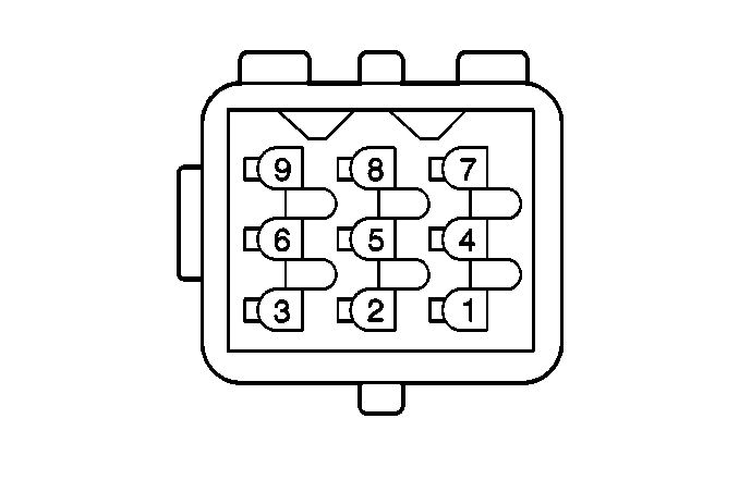
| |||||||
|---|---|---|---|---|---|---|---|
Connector Part Information |
| ||||||
Pin | Wire Color | Circuit No. | Function | ||||
1 | BRN/RED | XA40 | Pedal Position 2 Signal Return | ||||
2 | BRN/GRY | XR24 | Pedal Position 1 Reference Ground | ||||
3 | -- | -- | Not Used | ||||
4 | BLK/GRY | FR56 | Pedal Position 1 5V Reference | ||||
5 | BRN/BLK | XF8 | Pedal Position 1 Signal Return | ||||
6 | BRN/GRN | XU800 | Ground | ||||
7 | -- | -- | Not Used | ||||
8 | BRN/RED | FA7 | Pedal Position 2 5V Reference | ||||
9 | -- | -- | Not Used | ||||
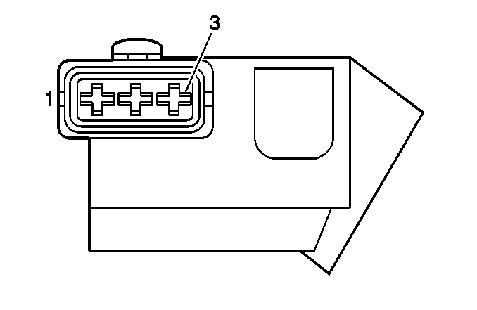
| |||||||
|---|---|---|---|---|---|---|---|
Connector Part Information |
| ||||||
Pin | Wire Color | Circuit No. | Function | ||||
1 | BRN/GRN | XU306 | Sensor Ground | ||||
2 | WHT | M381 | CMP Sensor Signal Output | ||||
3 | RED/BLU | AP800 | Switched Battery Positive Voltage | ||||
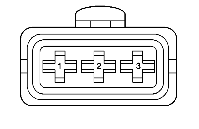
| |||||||
|---|---|---|---|---|---|---|---|
Connector Part Information |
| ||||||
Pin | Wire Color | Circuit No. | Function | ||||
1 | GRY/BLK | RF78 | CKP Signal High Output | ||||
2 | GRY/RED | RA20 | CKP Signal Low Output | ||||
3 | BLK | S03 | Shielded Ground | ||||
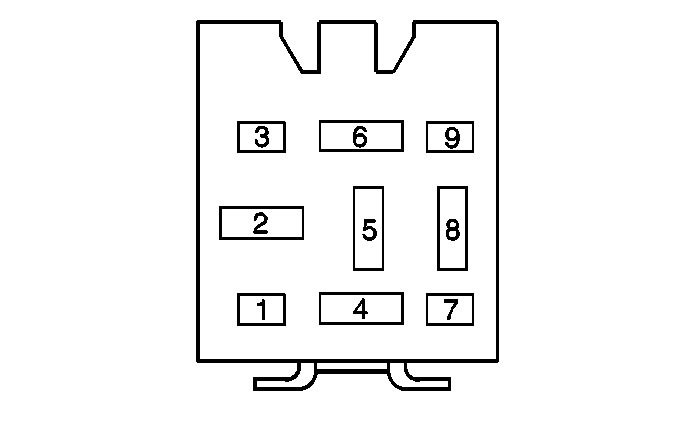
| |||
|---|---|---|---|
Connector Part Information | ZF 9-31 | ||
Pin | Wire Color | Circuit No. | Function |
1 | -- | -- | Not Used |
2 | RED | A71 | Fused Battery Feed |
3 | -- | -- | Not Used |
4 | RED | A73 | Fused Battery Feed |
5 | -- | -- | Not Used |
6 | BRN/GRY | XR31 | Relay K43 Control |
7 | -- | -- | Not Used |
8 | RED/BLU | AP75 | Switched B+ From Relay K43 |
9 | -- | -- | Not Used |
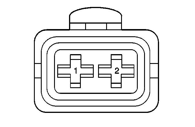
| |||||||
|---|---|---|---|---|---|---|---|
Connector Part Information |
| ||||||
Pin | Wire Color | Circuit No. | Function | ||||
1 | BRN/BLU | XP74 | ECT Sensor Signal | ||||
2 | BRN/GRN | XU715 | Sensor Ground | ||||
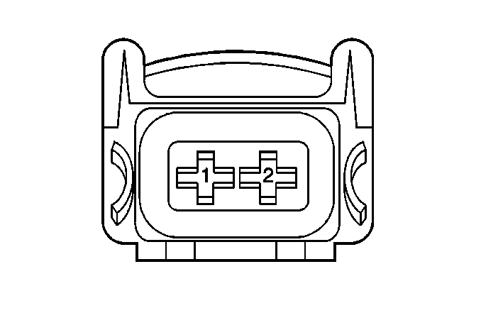
| |||||||
|---|---|---|---|---|---|---|---|
Connector Part Information |
| ||||||
Pin | Wire Color | Circuit No. | Function | ||||
1 | RED/BLU | AP108 | B+ From Relay K43 | ||||
2 | BRN/RED | XA61 | EVAP Purge Solenoid Valve Control | ||||

| |||||||
|---|---|---|---|---|---|---|---|
Connector Part Information |
| ||||||
Pin | Wire Color | Circuit No. | Function | ||||
1 | RED/BLU | AP88 | B+ From Relay K43 | ||||
2 | BRN/BLK | XF888 | EVAP Vent Solenoid Valve | ||||
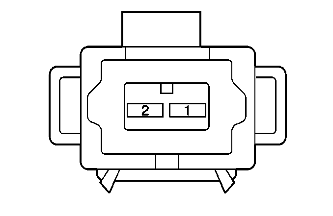
| |||
|---|---|---|---|
Connector Part Information | ZFW 2-44 | ||
Pin | Wire Color | Circuit No. | Function |
1 | RED/BLU | AP61 | B+ From Relay K43 |
2 | BRN/YEL | XB17 | Fuel Injector #1 Control |

| |||
|---|---|---|---|
Connector Part Information | ZFW 2-44 | ||
Pin | Wire Color | Circuit No. | Function |
1 | RED/BLU | AP63 | B+ From Relay K43 |
2 | BRN/GRN | XU16 | Fuel Injector #2 Control |

| |||
|---|---|---|---|
Connector Part Information | ZFW 2-44 | ||
Pin | Wire Color | Circuit No. | Function |
1 | RED/BLU | AP64 | B+ From Relay K43 |
2 | BRN/BLU | XP35 | Fuel Injector #3 Control |

| |||
|---|---|---|---|
Connector Part Information | ZFW 2-44 | ||
Pin | Wire Color | Circuit No. | Function |
1 | RED/BLU | AP62 | B+ From Relay K43 |
2 | BRN/RED | XA34 | Fuel Injector #4 Control |

| |||
|---|---|---|---|
Connector Part Information | ZFW 2-44 | ||
Pin | Wire Color | Circuit No. | Function |
1 | RED/BLU | AP65 | B+ From Relay K43 |
2 | BRN/BLK | XF15 | Fuel Injector #5 Control |

| |||
|---|---|---|---|
Connector Part Information | ZFW 2-44 | ||
Pin | Wire Color | Circuit No. | Function |
1 | RED/BLU | AP66 | B+ From Relay K43 |
2 | BRN/PPL | XY33 | Fuel Injector #6 Control |
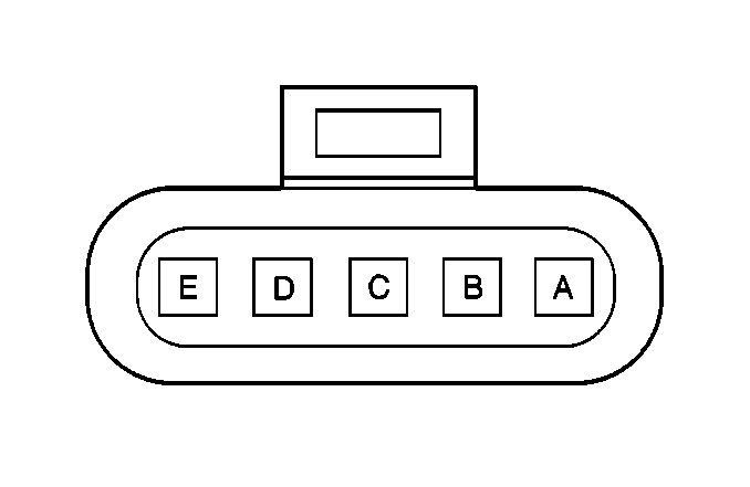
| |||
|---|---|---|---|
Connector Part Information | ZFW 5-3 | ||
Pin | Wire Color | Circuit No. | Function |
A | RED/BLU | AP10 | B+ From FUEL PUMP Fuse |
B | BLK | F224 | Ground to G103 |
C | BLK | F30 | Ground to G400 |
D | BLU/BLK | PF11 | Fuel Level Signal |
E | Not Used | ||

| |||
|---|---|---|---|
Connector Part Information | ZF 9-31 | ||
Pin | Wire Color | Circuit No. | Function |
1 | -- | -- | Not Used |
2 | RED | A72 | Fused Battery Feed |
3 | -- | -- | Not Used |
4 | RED/BLU | AP76 | B+ From Relay K43 |
5 | -- | -- | Not Used |
6 | BRN/BLU | XR3 | Relay Control Signal |
7 | -- | -- | Not Used |
8 | RED/BLU | AP77 | B+ Feed to FUEL PUMP Fuse |
9 | -- | -- | Not Used |

| |||||||
|---|---|---|---|---|---|---|---|
Connector Part Information |
| ||||||
Pin | Wire Color | Circuit No. | Function | ||||
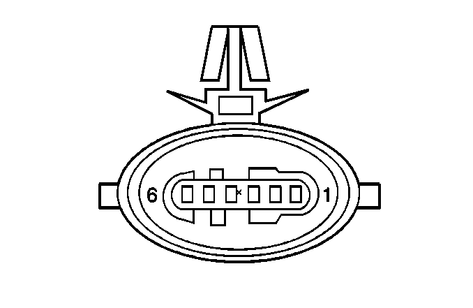
1 | BLU/BLK | PF1 | 5V Reference | ||||
2 | BRN/GRN | XU1 | Sensor Ground | ||||
3 | BRN/YEL | XB1 | Fuel Pressure Sensor Signal | ||||
| |||
|---|---|---|---|
Connector Part Information | ZFW 6-15 | ||
Pin | Wire Color | Circuit No. | Function |
1 | BRN/RED | XA43 | Lambda Sensor Pump Current Input |
2 | BRN/BLU | XP19 | HO2S Signal |
3 | BRN/WHT | XM30 | HO2S Reference Ground |
4 | BRN/GRY | XR11 | HO2S Heater Control |
5 | RED/BLU | AP122 | Fused Battery Feed |
6 | BRN/GRN | XU462 | Lambda Sensor Pump Current Output |

| |||
|---|---|---|---|
Connector Part Information | ZFW 6-15 | ||
Pin | Wire Color | Circuit No. | Function |
1 | BRN/RED | XA610 | Lambda Sensor Pump Current Input |
2 | BRN/BLU | XP18 | HO2S Signal |
3 | BRN/WHT | XM309 | HO2S Reference Ground |
4 | BRN/GRY | XR61 | HO2S Heater Control |
5 | RED/BLU | AP124 | Fused Battery Feed |
6 | BRN/GRN | XU464 | Lambda Sensor Pump Current Output |
| |||
|---|---|---|---|
Connector Part Information | ZFW 4-2 | ||
Pin | Wire Color | Circuit No. | Function |
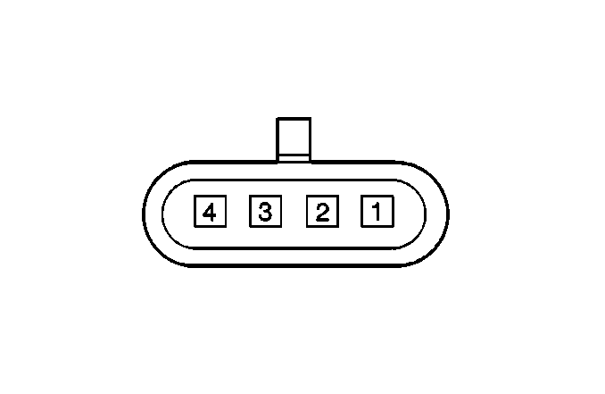
1 | RED/BLU | AP950 | Fused Battery Feed |
2 | BRN/WHT | XM950 | HO2S Heater Control |
3 | BRN/GRN | XU960 | HO2S Reference Ground |
4 | BRN/BLU | XP960 | HO2S Signal |

| |||
|---|---|---|---|
Connector Part Information | ZFW 4-2 | ||
Pin | Wire Color | Circuit No. | Function |
1 | RED/BLU | AP951 | Fused Battery Feed |
2 | BRN/WHT | XM951 | HO2S Heater Control |
3 | BRN/GRN | XU950 | HO2S Reference Ground |
4 | BRN/BLU | XP961 | HO2S Signal |
| |||||||
|---|---|---|---|---|---|---|---|
Connector Part Information |
| ||||||
Pin | Wire Color | Circuit No. | Function | ||||
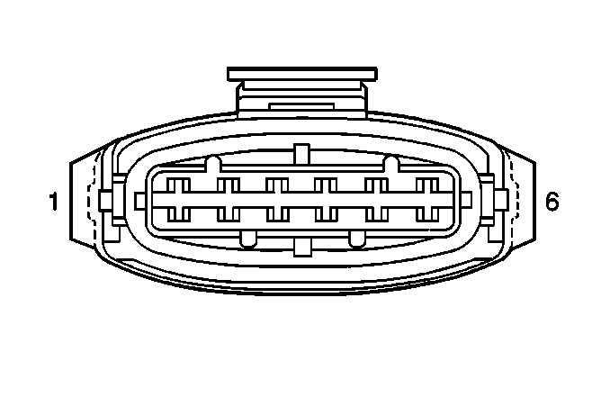
1 | BLK | F60 | Ground | ||||
2 | BRN | X69 | Switched Ignition Feed | ||||
3 | GRY/BLK | RF51 | Cyl. 6 Ignition Control | ||||
4 | BLK/YEL | FB61 | Cyl. 4 Ignition control | ||||
5 | BLK/RED | FA71 | Cyl. 2 Ignition Control | ||||
6 | -- | -- | Not Used | ||||
| |||||||
|---|---|---|---|---|---|---|---|
Connector Part Information |
| ||||||
Pin | Wire Color | Circuit No. | Function | ||||
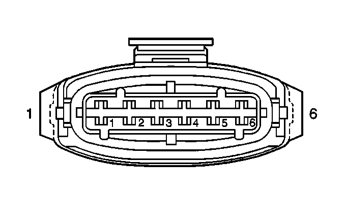
1 | BLK | F50 | Ground | ||||
2 | BRN | X68 | Switched Ignition Feed | ||||
3 | GRY/BLK | RF50 | Cyl. 5 Ignition Control | ||||
4 | BLK/YEL | FB60 | Cyl. 3 Ignition Control | ||||
5 | BLK/RED | FA70 | Cyl. 1 Ignition Control | ||||
6 | -- | -- | Not Used | ||||
| |||
|---|---|---|---|
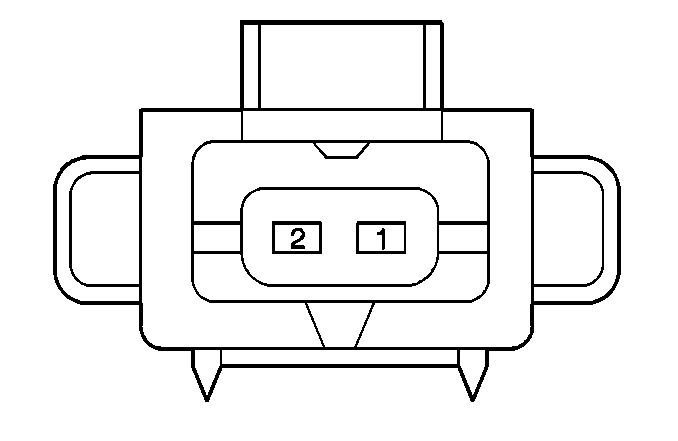
Connector Part Information | ZFW 2-40 | ||
Pin | Wire Color | Circuit No. | Function |
1 | BRN/GRN | XU35 | Intake Plenum Switch-Over Solenoid Valve Control |
2 | RED/BLU | AP105 | B+ From Relay K43 |
| |||
|---|---|---|---|
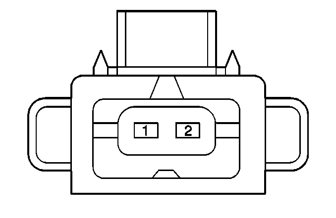
Connector Part Information | ZFW 2-40 | ||
Pin | Wire Color | Circuit No. | Function |
1 | BRN/GRN | XU7 | Intake Resonance Switch-Over Solenoid Valve Control |
2 | RED/BLU | AP104 | B+ From Relay K43 |

| |||
|---|---|---|---|
Connector Part Information | ZFW 2-83 | ||
Pin | Wire Color | Circuit No. | Function |
1 | BRN/WHT | XM70 | KS Bank 1 Signal |
2 | BRN/GRN | XU420 | KS Reference Ground |

| |||
|---|---|---|---|
Connector Part Information | ZFW 2-83 | ||
Pin | Wire Color | Circuit No. | Function |
1 | BRN/WHT | XM40 | KS Bank 2 Signal |
2 | BRN/GRN | XU410 | KS Reference Ground |
| |||||||
|---|---|---|---|---|---|---|---|
Connector Part Information |
| ||||||
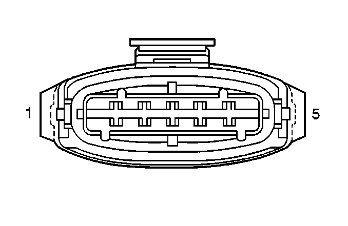
Pin | Wire Color | Circuit No. | Function | ||||
1 | BRN/BLK | XF30 | IAT Sensor Signal | ||||
2 | RED/BLU | AP84 | B+ From Relay K43 | ||||
3 | BRN/GRN | XU304 | Sensor Ground | ||||
4 | BLU/BLK | PF107 | 5 V Reference | ||||
5 | GRY/RED | RA40 | MAF Sensor Signal | ||||
| |||
|---|---|---|---|
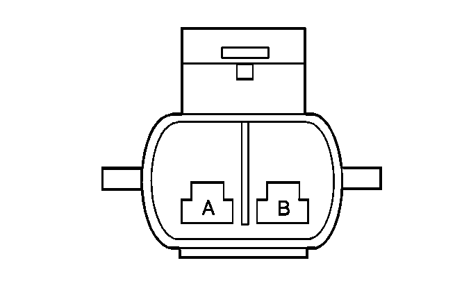
Connector Part Information | ZFW 2-24 | ||
Pin | Wire Color | Circuit No. | Function |
A | PPL | Y110 | Pump ON Signal |
B | BLK | F110 | Ground to G104 |

| |||
|---|---|---|---|
Connector Part Information | ZF 9-32 | ||
Pin | Wire Color | Circuit No. | Function |
1 | -- | -- | Not Used |
2 | PPL | Y110 | Pump ON Signal |
3 | -- | -- | Not Used |
4 | RED/BLU | AP200 | B+ From Relay K43 |
5 | BLK | F200 | Ground to G103 |
6 | BRN/GRY | XR200 | Relay Control |
7 | -- | -- | Not Used |
8 | RED | A730 | Fused Battery Feed |
9 | -- | -- | Not Used |

| |||
|---|---|---|---|
Connector Part Information | ZFW 2-35 | ||
Pin | Wire Color | Circuit No. | Function |
1 | RED/BLU | AP952 | B+ From Relay K43 |
2 | BRN/YEL | XB952 | Solenoid Valve Control |
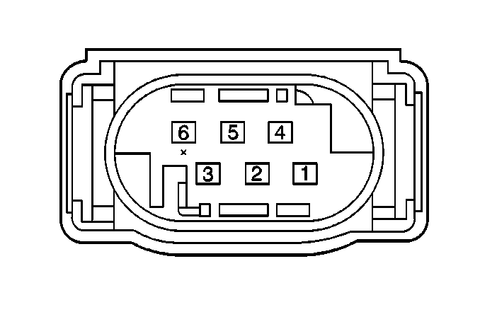
| |||||||
|---|---|---|---|---|---|---|---|
Connector Part Information |
| ||||||
Pin | Wire Color | Circuit No. | Function | ||||
1 | BLK/WHT | FM10 | Throttle Valve Motor Ground | ||||
2 | BRN/GRN | XU30 | Sensor Ground | ||||
3 | BLU/BLK | PF102 | 5 V Reference | ||||
4 | BRN/YEL | XB10 | Throttle Valve Motor Power | ||||
5 | BRN/BLU | XP53 | TP Sensor 2 Signal | ||||
6 | WHT | M24 | TP Sensor 1 Signal | ||||

| |||||||||||||||
|---|---|---|---|---|---|---|---|---|---|---|---|---|---|---|---|
Connector Part Information |
| Connector Part Information |
| ||||||||||||
Pin | Wire Color | Circuit No. | Function | Pin | Wire Color | Circuit No. | Function | ||||||||
A | BRN/YEL | XB17 | Fuel Injector #1 Control | A | BRN/YEL | XB17 | Fuel Injector #1 Control | ||||||||
B | BRN/GRN | XU16 | Fuel Injector #2 Control | B | BRN/GRN | XU16 | Fuel Injector #2 Control | ||||||||
C | BRN/BLU | XP35 | Fuel injector #3 control | C | BRN/BLU | XP35 | Fuel injector #3 control | ||||||||
D | BRN/RED | XA34 | Fuel Injector #4 Control | D | BRN/RED | XA34 | Fuel Injector #4 Control | ||||||||
E | BRN/BLK | XF15 | Fuel Injector #5 Control | E | BRN/BLK | XF15 | Fuel Injector #5 Control | ||||||||
F | BRN/PPL | XY33 | Fuel Injector #6 Control | F | BRN/PPL | XY33 | Fuel Injector #6 Control | ||||||||
G | RED/BLU | AP751 | B+ from Relay K43 | G | RED/BLU | AP751 | B+ from Relay K43 | ||||||||
