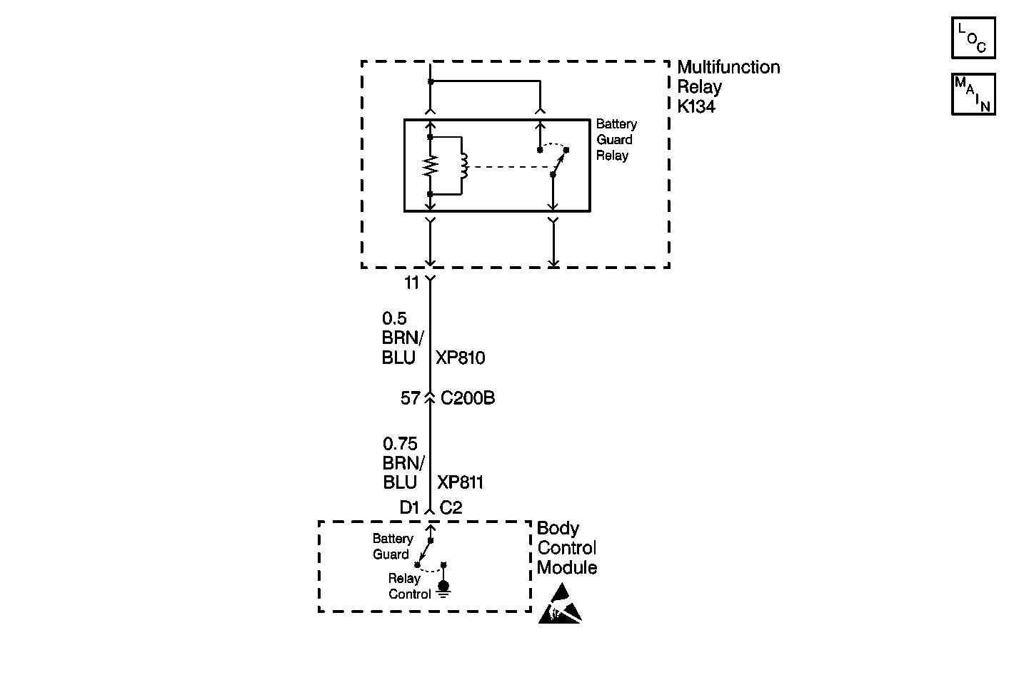
Circuit Description
The body control module (BCM) controls the battery guard relay by grounding the relay coil at terminal D1. Once the relay is energized, the relay supplies battery power to the following components:
| • | The radio receiver |
| • | The radio interface module (RIM) |
| • | The fuel tank filler door relay coil |
| • | The rear compartment lid release relay coil |
| • | The cellular telephone (if equipped) |
When the ignition switch is turned to the LOCK position the BCM transitions to the High Power Mode. In this mode, the BCM is still in control of the battery guard relay and will continue to supply battery power for 15 minutes to the previously mentioned components.
The 15 minute time period is restarted when the BCM receives the following inputs:
| • | An ignition switch transition (LOCK to ON) has occured while the BCM was asleep. |
| • | The BCM is awake (with the ignition in the LOCK position) and any of the following has occured: |
| - | The trunk is opened or closed. |
| - | A door is opened or closed. |
| - | A RFA-Button report is received (Class 2 or RF message). |
| - | The key is placed in the ignition. |
| - | The interior light switch is activated. |
| • | The BCM is awake and the ignition switch transitions from ON to LOCK. |
Conditions for Setting the DTC
The BCM monitors the output to the battery guard relay every second at terminal D1. The fault code is set when the feedback goes high (short to B+) for 2 or more seconds.
Action Taken When the DTC Sets
| • | The High Power Mode is deactivated. |
| • | Stores a DTC B1973 in the BCM memory. |
Conditions for Clearing the DTC
| • | The BCM does not detect the malfunction for one monitoring cycle. |
| • | A history DTC will clear after 50 consecutive ignition cycles if the fault is no longer present. |
| • | The use of a scan tool. |
Diagnostic Aids
| • | Refer to the relay box end view for terminal assignments when the diagnostics direct you to take electrical measurements at the relay box. The end view is located in Power and Grounding Component Views in Wiring Systems. |
| • | Test the following if the problem is intermittent: |
| - | A damaged wiring harness. Inspect the wiring harness for damage. |
| - | If the wiring harness appears to be in good condition, observe the display on the DMM while moving connectors and wiring harnesses related to the BCM. |
| - | Inspect the wiring harness connectors for backed out terminals, improper mating, improperly formed or damaged terminals, and poor wire terminal to wire connections. |
| • | For additional information, refer to Intermittents and Poor Connections Diagnosis in Wiring Systems. |
Test Description
The following numbers refer to the step numbers on the diagnostic table:
-
This step tests for a circuit problem (short to B+) external to the BCM.
-
This step tests the circuit for an intermittent condition because the problem is not current at this time. After testing the circuit and making any necessary repairs, test the BCM again to see if the DTC resets.
Step | Action | Value(s) | Yes | No |
|---|---|---|---|---|
1 | Did you perform the BCM Diagnostic System Check? | -- | Go to Step 2 | |
Is the measured voltage reading less than the specified value? | 1.0 V | Go to Step 3 | Go to Step 4 | |
Is a current DTC B1973 set? | -- | Go to Step 2 | System OK | |
4 | Locate and repair the short to B+ in CKT XP810. Is the repair complete? | -- | Go to Step 6 | -- |
5 | Replace the BCM. Refer to Body Control Module Replacement . Is the replacement complete? | -- | Go to Step 6 | -- |
6 |
Does the BCM operate properly? | -- | System OK |
