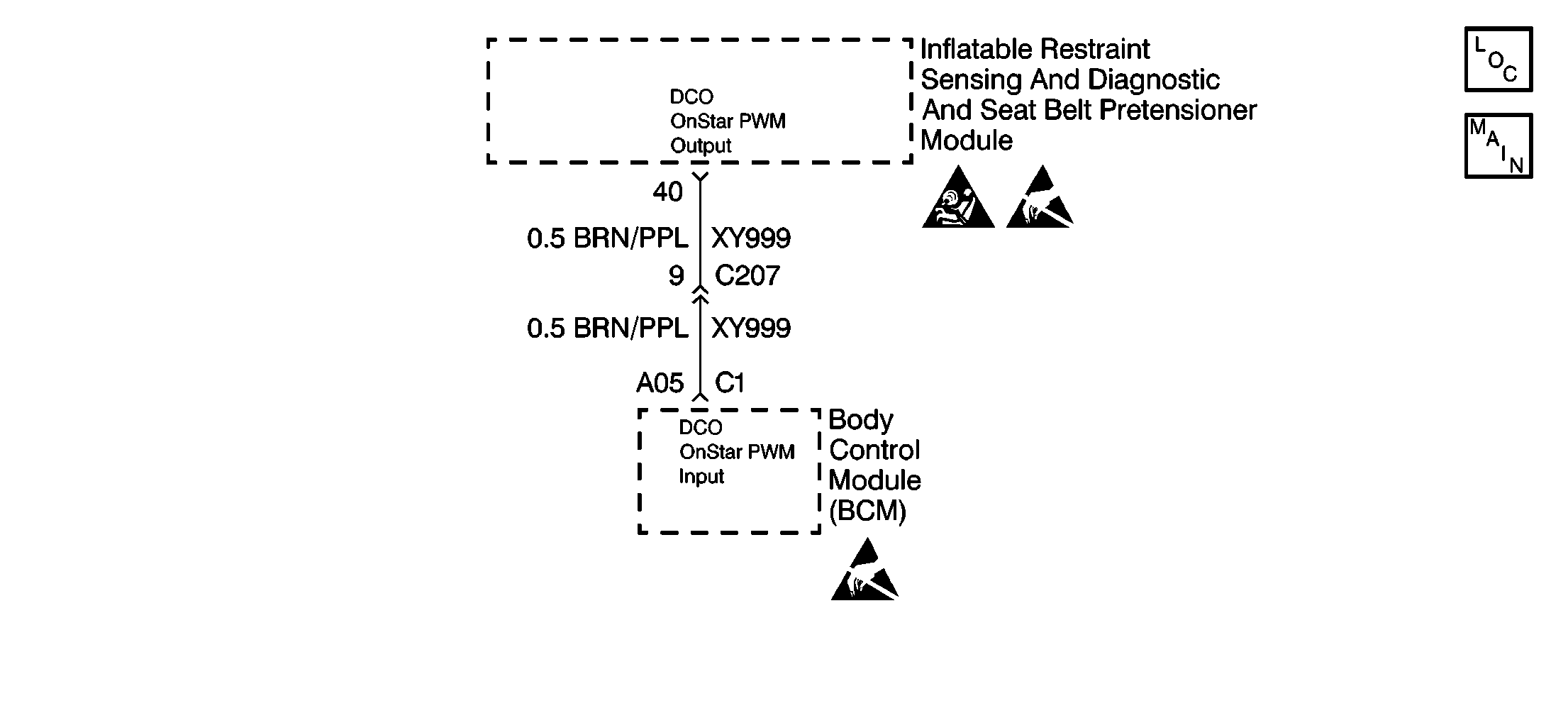
Circuit Description
The inflatable restraint sensing and diagnostic and seat belt pretensioner module (SDM) performs tests to diagnose critical malfunctions within itself when the ignition switch is turned ON. The SDM is hard-wired to the body control module (BCM) through CKT XY999. When the ignition switch is turned to the ON position, the SDM sends fixed frequency pulses to the BCM. In the event of a collision involving air bag deployment, the SDM sends higher frequency pulses to the BCM, which in turn sends a Class 2 message to the ONSTAR module. Upon receiving the Class 2 message, the ONSTAR module transmits a deployment commanded output (DCO) signal to the service center via the vehicle's cellular telephone. The SDM monitors CKT XY999 to detect leakage currents to voltage and open circuits in the (DCO) link to the BCM. The SDM service wait time is 1 minute. Refer to ENABLE/DISABLE procedures.
Conditions for Setting the DTC
DTC 97 will set when the following conditions are met:
| • | The ignition is within the normal operating voltage range. |
| • | A short to B+ in CKT XY999. |
| • | An open or a high resistance in CKT XY999. |
Action Taken When the DTC Sets
| • | The SDM sets a DTC 97. |
| • | The SDM turns ON the AIR BAG warning lamp. |
Conditions for Clearing the DTC
Current and History DTC codes must be cleared using a scan tool Clear DTC Information command. If the circuit fault has been successfully repaired and the conditions which caused the DTC to set are no longer existing, the DTC may be cleared using the scan tool.
Diagnostic Aids
A short to B+ or an open or a high resistance in CKT XY999 can cause an intermittent condition. Inspect CKT XY999 carefully for cutting and/or chafing. A careful inspection of the circuit and components indicated on the DTC 97 table is essential to make sure that the SDM and/or BCM will not be unnecessarily replaced.
Test Description
-
This step checks the inflatable restraint sensing and diagnostic and seat belt pretensioner module (SDM) wiring harness connector for damaged terminals or corrosion.
-
This step checks the inflatable restraint sensing and diagnostic and seat belt pretensioner module (SDM) for damaged terminals or corrosion.
-
This step checks the body control module (BCM) wiring harness connector C1 for damaged terminals or corrosion.
-
This step checks the body control module (BCM) for damaged terminals or corrosion.
-
This step checks for an open or a high resistance in CKT XY999.
-
This step checks for a short to B+ in CKT XY999.
-
This step determines if there is a malfunctioning BCM or if there is a malfunctioning SDM.
Step | Action | Value(s) | Yes | No |
|---|---|---|---|---|
1 | Was the SIR Diagnostic System Check performed? | -- | ||
Is the terminal 40 of the SDM wiring harness connector damaged or corroded? | -- | |||
3 | Use the J 42250 Catera Terminal Repair Kit to repair the SDM wiring harness connector. Is the repair complete? | -- | -- | |
Inspect terminal 40 of the SDM for damaged terminals or corrosion. Is the terminal 40 of the SDM damaged or corroded? | -- | |||
5 | Replace the SDM. Refer to Inflatable Restraint Sensing and Diagnostic and Seat Belt Pretensioner Module Replacement . Is the repair complete? | -- | -- | |
Is terminal A05 of the BCM wiring harness connector C1 damaged or corroded? | -- | |||
7 | Repair the BCM wiring harness connector C1. Refer to Connector Repairs in Wiring Systems. Is the repair complete? | -- | -- | |
Inspect terminal A05 of the BCM for damaged terminals or corrosion. Is terminal A05 of the BCM damaged or corroded? | -- | |||
9 | Replace the BCM. Refer to Body Control Module Replacement in Body Control System. Is the repair complete? | -- | -- | |
Use the J 39200 Digital Multimeter (DMM) to measure the resistance between terminal A05 of the BCM wiring harness connector C1 and terminal 40 of the SDM wiring harness connector. Is the measured resistance within the specified value? | 0-2 ohms | |||
11 |
Is the repair complete? | -- | -- | |
Is the measured voltage more than the specified value? | 1 V | |||
13 |
Is the repair complete? | -- | -- | |
Does the ONSTAR test flag display SET and the ONSTAR signal display OK? | -- | |||
15 | Replace the BCM. Refer to Body Control Module Replacement in Body Control System. Is the repair complete? | -- | -- | |
16 | Reconnect all the SIR components, making sure all the components are properly mounted? Have all the SIR components been reconnected and properly mounted? | -- | -- | |
17 | Use the scan tool to clear all SIR and BCM current and history DTCs. Have all SIR and BCM current and history DTCs been cleared? | -- | -- |
