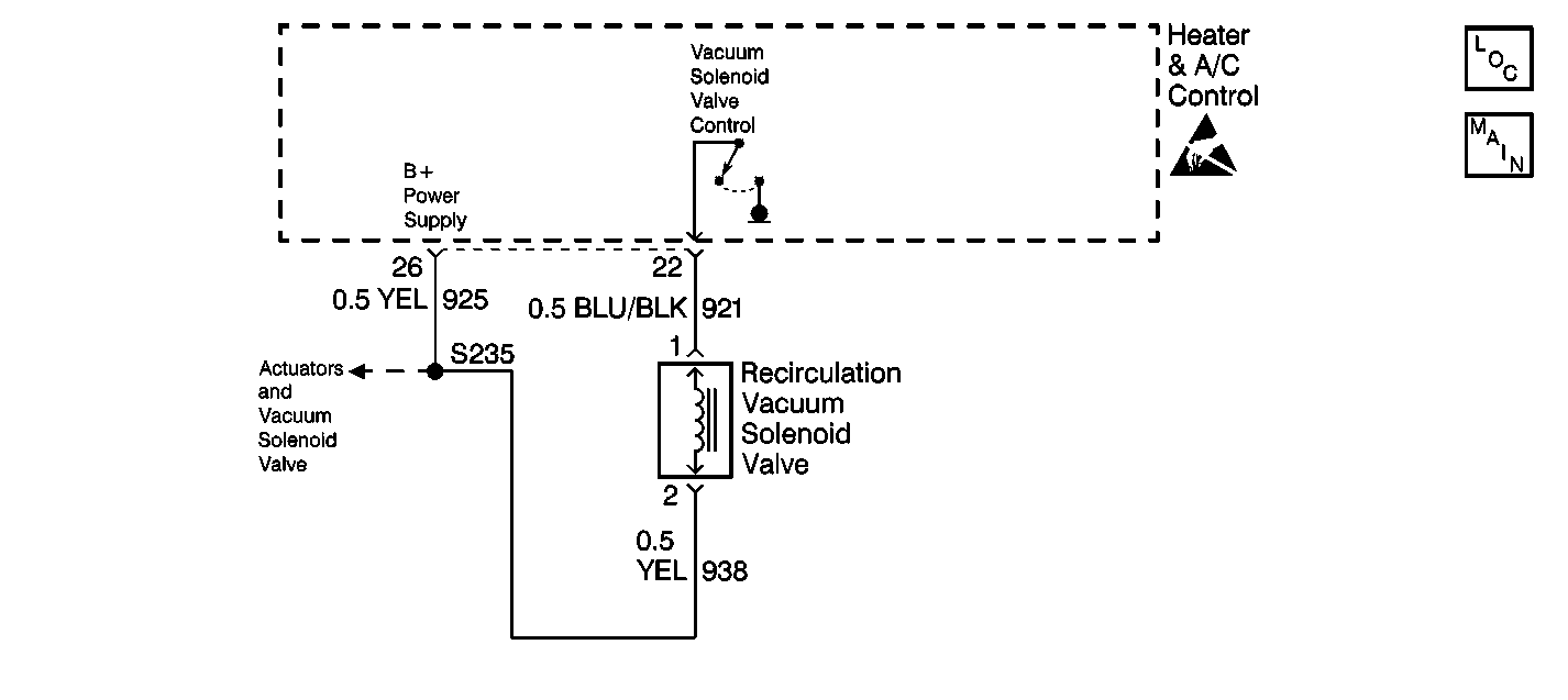
DTC 29 Air Circulation Valve Voltage High 2nd Design

Circuit Description
The recirculation switch on the control panel is a momentary switch that returns to the rest position after it is pressed to the ON or OFF positions. When it is pressed to the ON position, the heater and A/C control grounds the coil of the recirculation vacuum solenoid valve. Battery voltage is supplied from the heater and A/C control to the solenoid, when the ignition is in the ON position. With voltage supplied and ground provided the solenoid energizes, and allows vacuum to flow to the recirculation actuator valve.
The heater and A/C control also controls the solenoid valve in the AUTO mode.
Conditions for Setting the DTC
| • | If a short circuit to battery is detected on a low side driver, the controller automatically protects the low side driver by disabling all low side outputs. |
| • | A short to battery has been detected on CKT 921. |
Action Taken When the DTC Sets
| • | Stores a DTC 29 in the heater and A/C control memory. |
| • | The fault detection process is repeated 3 times at a fixed interval of 70 ms to allow for debouncing. |
| • | The heater and A/C control disables the output internally. |
Conditions for Clearing the DTC
| • | The conditions for the fault are no longer present. |
| • | Using a scan tool. |
| • | A history DTC will clear after 20 consecutive ignition cycles if the conditions for the fault is no longer present. |
Diagnostic Aids
| • | If the DTC is a history or an intermittent. Try to perform the tests shown while moving the harness wiring and connectors, this can often cause the malfunction to appear. |
| • | When moving related harnesses and harness connectors, visually/physically inspect wiring and connectors for the following: |
| - | Dirt or corrosion on the terminals. The terminals must be clean and free of any foreign material which could impede proper terminal contact. |
| - | Damaged connector body, exposing the terminals to moisture and dirt, as well as not maintaining proper terminal orientation with the component or mating connector. |
| - | Wire insulation which is rubbed through, causing an intermittent short as the bare area touches other wiring or parts of the vehicle. |
| • | Check the power and ground circuits before replacing the heater and A/C control. |
Test Description
The numbers below refer to the step numbers on the diagnostic table.
Step | Action | Value(s) | Yes | No |
|---|---|---|---|---|
1 | Was the Air Delivery System Check performed? | -- | ||
Is the voltage within the specified value? | Less than 0.1 V | |||
3 | The problem may be intermittent. Move related harnesses and harness connectors. Refer to Diagnostic Aids. Was a problem found and repaired? | -- | ||
4 | Locate and repair short to B+ in CKT 921. Is the repair complete? | -- | -- | |
5 |
Is a current DTC 29 set? | -- | ||
6 | Replace and reprogram the heater and A/C control. Refer to Control Assembly Replacement . Is the replacement and programming complete? | -- | -- |
