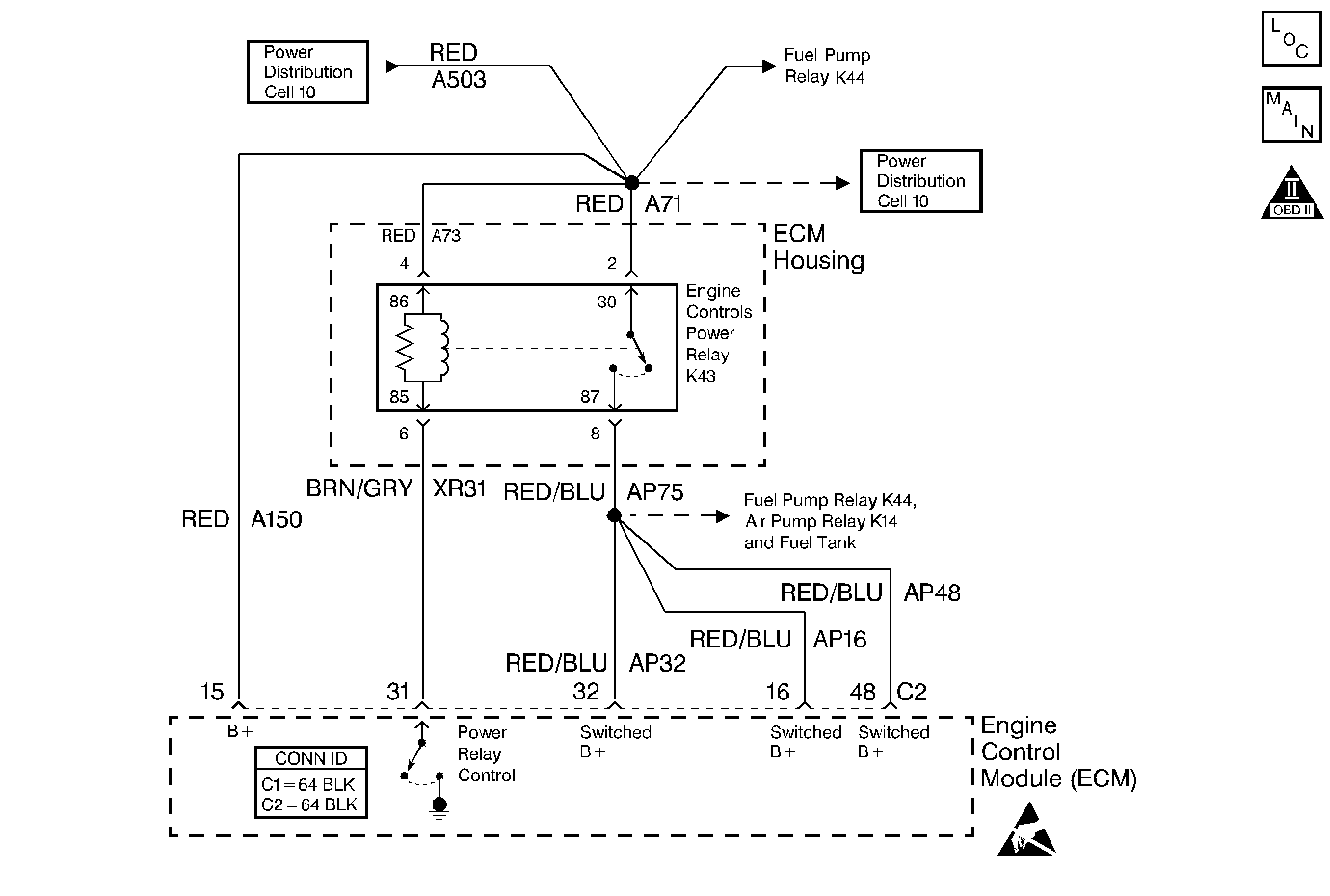
Circuit Description
The ECM continuously monitors the system voltage. Since voltages that are below 10.0 volts or more than 17 volts could cause an improper system operation and/or component damage, the ECM operates in a default mode if an ECM Voltage DTC is set. If the system voltage is low, the ECM will raise the idle speed in order to increase the generator output. If the system voltage is high, the ECM disables most outputs in order to protect the hardware. The Serial Data is disrupted when the system voltage is below 10 volts or more than 16 volts. A scan tool may not display the data if the system voltage is outside of this range.
Conditions for Running the DTC
The vehicle speed is more than 0 km/h.
Conditions for Setting the DTC
The system voltage measured at the ECM is less than 10 volts for 200 ms.
OR
The system voltage measured at the ECM is more than 17 volts for 200 ms.
Action Taken When the DTC Sets
| • | The ECM will not illuminate the malfunction indicator lamp (MIL). |
| • | The ECM will record operating conditions in Freeze Frame on the first drive trip that the diagnostic runs and fails (Fail Pending). |
Conditions for Clearing the MIL/DTC
| • | A History DTC clears after forty consecutive warm-up cycles if no failures report by this diagnostic or any other emission related diagnostic. |
| • | The ECM battery voltage is interrupted. |
| • | The scan tool clears the MIL/DTC. |
Diagnostic Aids
| • | An extremely low voltage (below 7.5 volts) may cause the loss of serial data and the MIL may not function. A low system voltage may cause the other DTCs to set. |
| • | Using the Freeze Frame data may aid in locating an intermittent condition. If the DTC cannot be duplicated, review the information in the Freeze Frame. Try to operate the vehicle within the same freeze frame conditions (the RPM, the MAF, the vehicle speed, the temperature, etc.) that were noted. This process may help in order to recreate the malfunction. |
Test Description
The numbers below refer to the step numbers on the diagnostic table.
-
This step tests for excessive generator output. The voltage should remain less than 17.0 volts.
-
This step tests the charging system under load at idle. The voltage should remain more than 10.0 volts.
Step | Action | Values | Yes | No | ||||
|---|---|---|---|---|---|---|---|---|
1 | Did you perform the Powertrain On-Board Diagnostic (OBD) System Check? | -- | Go to Step 2 | |||||
Is the voltage more than the specified value? | 17 V | Go to Step 4 | Go to Step 3 | |||||
Is the voltage less than the specified value? | 10 V | Go to Step 5 | Go to Step 8 | |||||
4 |
Is the voltage more than the specified value? | 17 V | Go to Battery Check | Go to Step 8 | ||||
5 |
Is the voltage less than the specified value? | 10 V | Go to Battery Check | Go to Step 6 | ||||
6 |
Is the voltage less than the specified value? | 10 V | Go to Step 10 | Go to Step 7 | ||||
7 | Inspect for any faulty connections at the ECM. Did you find and correct a problem? | -- | Go to Step 11 | Go to Step 8 | ||||
8 |
Is this DTC set? | -- | Go to Step 9 | Go to Diagnostic Aids | ||||
9 |
Important:
Replace the ECM. Refer to Engine Control Module Replacement/Programming . Did you complete the replacement? | -- | Go to Step 9 | -- | ||||
10 | Repair the high resistance in the battery feed circuit to the ECM. Did you complete the repair? | -- | Go to Step 11 | -- | ||||
11 |
Does the scan tool indicate that the diagnostic Passed? | -- | Go to Step 12 | Go to Step 2 | ||||
12 | Does the scan tool display any additional, undiagnosed DTCs? | -- | Go to applicable DTC table | System OK |
