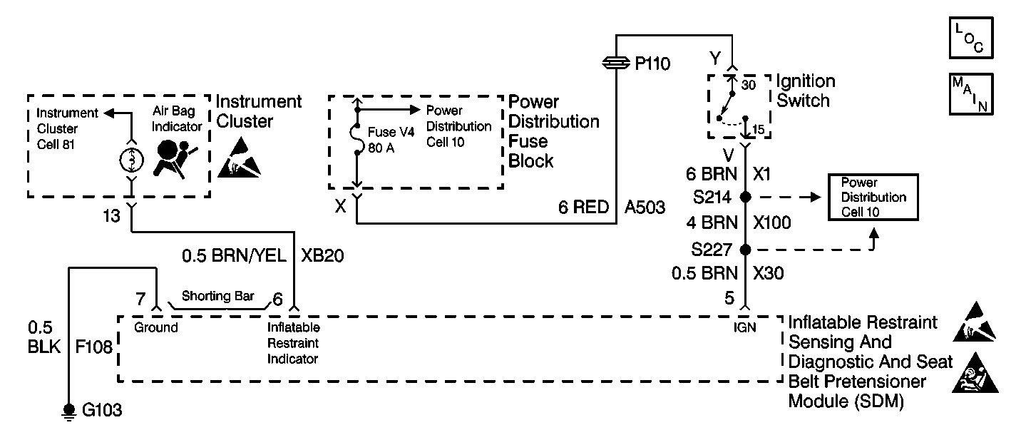
Circuit Description
When the ignition switch is turned to the ON position, the CLAMP 15 CRUISE Fuse applies battery voltage to the AIR BAG warning lamp that is connected to the INFLATABLE RESTRAINT INDICATOR, terminal 6, of the inflatable restraint sensing and diagnostic and seat belt pretensioner module (SDM). The ignition switch applies battery voltage to the IGNITION input, terminal 5, of the SDM. The SDM responds by flashing the AIR BAG Warning Lamp seven times and then turning it OFF. The SDM monitors the lamp output driver by comparing the output state at the INFLATABLE RESTRAINT INDICATOR, terminal 6, to the microprocessor commanded state.
Diagnostic Aids
In order to disable the shorting bar from terminal 6 to terminal 7 inside the inflatable restraint sensing and diagnostic and seat belt pretensioner module (SDM) wiring harness connector, the SDM wiring harness connector must be properly connected to the SDM.
When measurements are requested in this table, use J 39200 Digital Multimeter with the correct terminal adapter from J 35616 Connector Test Adapter Kit. When a check for proper connection is requested, refer to Intermittents and Poor Connections . When a wire, connector or terminal repair is requested, use J-38125 Terminal Repair Kit and refer to Wiring Repair .
Test Description
The numbers below refer to the step numbers on the diagnostic table:
-
This step checks to see if either DTC 43 or DTC 44 is present.
-
This step checks to see if sufficient voltage is being applied to the SDM.
-
This step checks to see if excessive voltage is being applied to the SDM.
-
This step checks to see if the connector position assurance (CPA) is properly installed.
-
This step checks to see if there is a malfunctioning shorting bar within the SDM wiring harness connector.
-
This step checks for a short to ground in CKT XB20.
-
This step determines if there is a short between CKT XB20 and CKT X30 or if there is a short to ground in CKT XB20.
-
This step checks to see if the SDM wiring harness connector is damaged or corroded.
-
This step determines if there is an open or a high resistance in CKT X30 or if there is a malfunctioning SDM.
Step | Action | Value(s) | Yes | No |
|---|---|---|---|---|
1 | Was the SIR Diagnostic System Check performed? | -- | ||
Is either DTC 43 or DTC 44 present? | -- | |||
3 |
Is the repair complete? | -- | -- | |
Use the scan tool to request the SIR data list display. Is the IGNITION more than the specified value? | 10 V | |||
Is the IGNITION more than the specified value? | 16 V | Go to Charging System Check in Engine Electrical | ||
Is the SDM CPA properly installed? | -- | |||
7 | Properly install the CPA. Is the repair complete? | -- | -- | |
8 |
Does the AIR BAG warning lamp come ON steady? | -- | ||
Is the shorting bar damaged or corroded? | -- | |||
10 | Use the J 42250 Catera Terminal Repair Kit to repair the SDM wiring harness connector. Is the repair complete? | -- | -- | |
Is the measured resistance less than the specified value? | OL | |||
Is the measured resistance less than the specified value? | OL | |||
13 |
Is the repair complete? | -- | -- | |
14 |
Is the repair complete? | -- | -- | |
15 | Replace the instrument cluster. Refer to Instrument Cluster Replacement in Instrument Panel, Gauges and Console. Is the repair complete? | -- | -- | |
Is terminal 5 of the SDM wiring harness connector damaged or corroded? | -- | |||
17 | Use the J 42250 Catera Terminal Repair Kit to repair the SDM wiring harness connector. Is the repair complete? | -- | -- | |
18 | Inspect terminal 5 of the SDM for damaged terminals or corrosion. Is terminal 5 of the SDM damaged or corroded? | -- | ||
19 | Replace the SDM. Refer to Inflatable Restraint Sensing and Diagnostic and Seat Belt Pretensioner Module Replacement . Is the repair complete? | -- | -- | |
Is the measured resistance within the specified value? | 0-2 ohms | |||
21 |
Is the repair complete? | -- | -- | |
22 | Reconnect all the SIR components, making sure that all the components are properly mounted. Have all SIR components been reconnected and properly mounted? | -- | -- | |
23 | Use the scan tool to clear all current and history SIR DTCs. Have all current and history SIR DTCs been cleared? | -- | -- |
