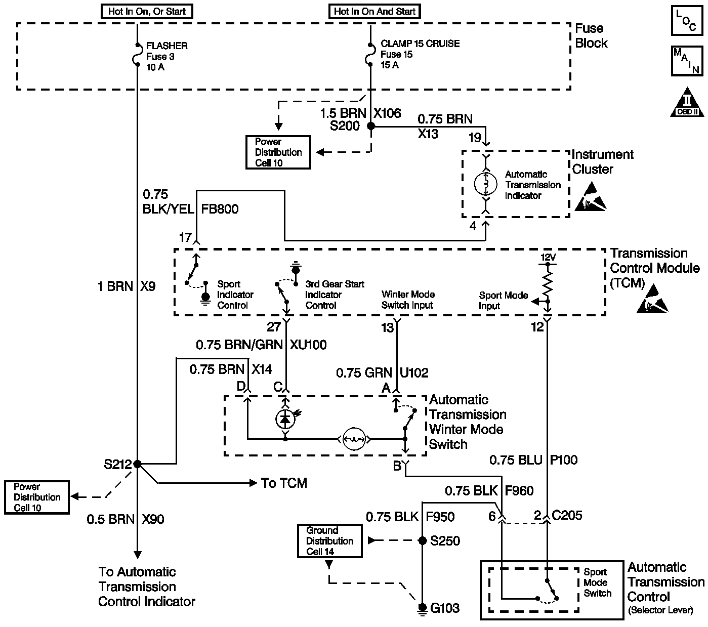
Circuit Description
The Winter Mode switch has two states of illumination. In normal operation, whenever the ignition switch is on, the snowflake symbol dimly illuminates from a bulb in the switch (the illumination lamp). When Winter Mode is active, an additional lamp (the indicator lamp) within the switch causes the snowflake symbol to illuminate brightly. With the engine running and the transmission in Drive 4, the Winter Mode Indicator Lamp should transition from On to Off or from Off to On with each press of the Winter Mode Selector Switch. The ignition voltage supplies directly to the indicator bulb. The transmission control module (TCM) controls the lamp by grounding the control circuit via an internal solid state device called a driver. The Winter Mode Selector Switch signal circuit is pulled up to B+ within the TCM. The other side of the switch connects to ground. When the switch is on, the signal voltage pulls low. The TCM interprets this signal voltage as a Winter mode request. The Winter mode selection causes the transmission to start in 3rd gear, improving the traction under slippery conditions.
Diagnostic Aids
An intermittent may be a result of the following conditions:
| • | Corrosion |
| • | Mis-routed harness |
| • | Rubbed through wire insulation |
| • | Broken wire inside the insulation |
Refer to Symptoms in Engine Controls for Intermittents.
Test Description
The number(s) below refer to the step number(s) on the diagnostic table.
-
The Winter Mode switch has 2 states of illumination. In normal operation, whenever the ignition switch is ON, the snowflake symbol dimly illuminates by a bulb in the switch (the illumination lamp). When the Winter Mode is active, an additional lamp (the indicator lamp) within the switch causes the snowflake symbol to illuminate brightly. If the switch illumination lamp is functioning, the feed circuit to the switch is OK.
Step | Action | Value(s) | Yes | No | ||||||
|---|---|---|---|---|---|---|---|---|---|---|
1 | Was the On-Board Diagnostic System Check check performed? | -- | ||||||||
2 | Any DTCs that are set must be corrected before performing this diagnostic procedure. Are there any DTCs set? | -- | Go to the applicable DTCs | |||||||
3 |
Caution: Apply the parking brake and block the drive wheels before performing this procedure in order to prevent bodily injury. Does the winter mode indicator lamp turn On and Off? | -- | Go to Diagnostic Aids | |||||||
4 |
Does the display change back and forth between On and Off? | -- | ||||||||
5 | Use the Scan Tool in order to command the winter mode indicator lamp On and Off. Does the lamp go On and Off? | -- | ||||||||
Is the indicator lamp always On? Refer to the test description. | -- | |||||||||
Is the switch illumination lamp On? Refer to the test description. | -- | |||||||||
8 |
Is the lamp On? | -- | ||||||||
9 | Check the winter mode circuit for one of the following conditions:
Refer to General Electrical Diagnosis in Wiring Systems. Is the action complete? | -- | -- | |||||||
10 |
Does the lamp illuminate? | -- | ||||||||
11 | Does the display always indicate On? | -- | ||||||||
12 |
Does the state change each time the jumper is momentarily connected? | -- | ||||||||
13 |
Does the J 39200 DMM indicate circuit continuity? | -- | ||||||||
14 | Use a fused jumper wire in order to connect the winter mode switch signal circuit to ground in the switch harness connector while observing the Scan Tool . Does the display indicate On? | -- | ||||||||
15 |
Is the resistance within the specified range? | 0-5ohms | ||||||||
16 | Repair the short to ground in the lamp control circuit. Is the action complete? | -- | -- | |||||||
17 | Repair the feed circuit to the instrument panel indicator lamps. Is the action complete? | -- | -- | |||||||
18 | Repair the signal circuit shorted to ground. Is the action complete? | -- | -- | |||||||
19 | Repair the open/high resistance signal circuit. Is the action complete? | -- | -- | |||||||
20 | Check the winter mode switch circuit for an open/high resistance ground. Was a condition found and corrected? | -- | ||||||||
21 | Replace the switch. Is the action complete? | -- | -- | |||||||
22 | Check the TCM harness connector for a poor connection or poor terminal tension. Refer to General Electrical Diagnosis in Wiring Systems. Was a condition found and corrected? | -- | ||||||||
23 | Replace the TCM. Refer to Transmission Control Module Replacement . Is the action complete? | -- | -- | |||||||
24 |
Caution: Apply the parking brake and block the drive wheels before performing this procedure in order to prevent bodily injury. Does the winter mode indicator lamp turn On and Off? | -- | System OK |
