| Table 1: | A/C Compressor Clutch Coil |
| Table 2: | A/C Compressor Relay K60 |
| Table 3: | A/C Load Switch |
| Table 4: | A/C Compressor Refrigerant Pressure Switch |
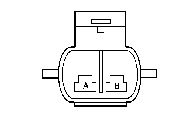
| Table 5: | Ambient Air Outside Temperature Sensor |
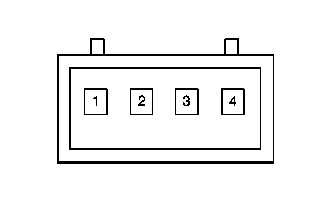
| Table 6: | Headlamp Automatic Control Ambient Light Sensor |
| Table 7: | Heater and A/C Control Connector C1 |
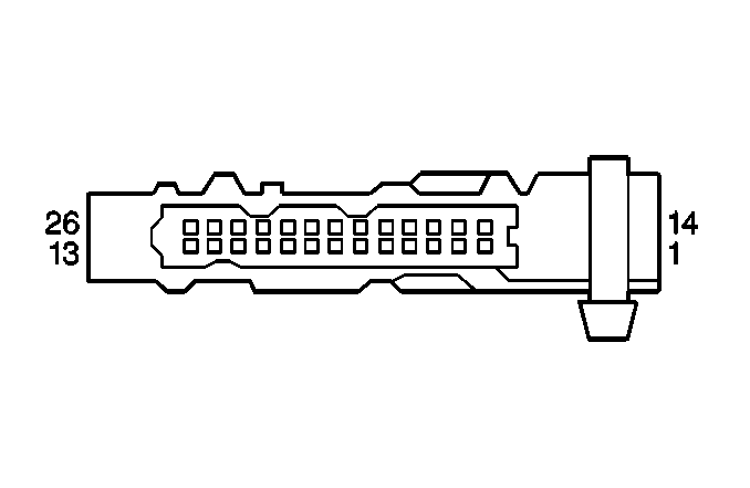
| Table 8: | Heater and A/C Control Connector C2 |
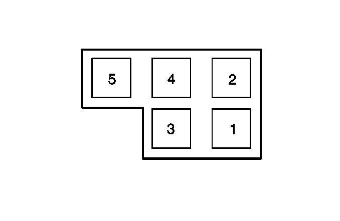
| Table 9: | Blower Control Module |
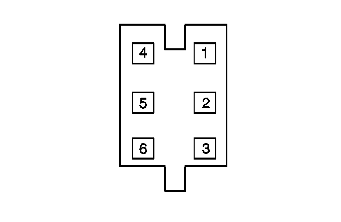
| Table 10: | Defroster Valve Actuator |
| Table 11: | Floor Air Valve Actuator (Mode Valve) |
| Table 12: | Inside Air Valve Actuator |
| Table 13: | Temperature Valve Actuator LH |
| Table 14: | Temperature Valve Actuator RH |
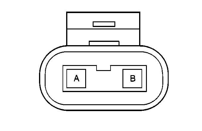
| |||||||
|---|---|---|---|---|---|---|---|
Connector Part Information |
| ||||||
Pin | Wire Color | Circuit No. | Function | ||||
A | BRN/BLK | XF102 | Clutch Coil Ground | ||||
B | GRN | U30 | Switched Battery Feed From Relay K60 | ||||
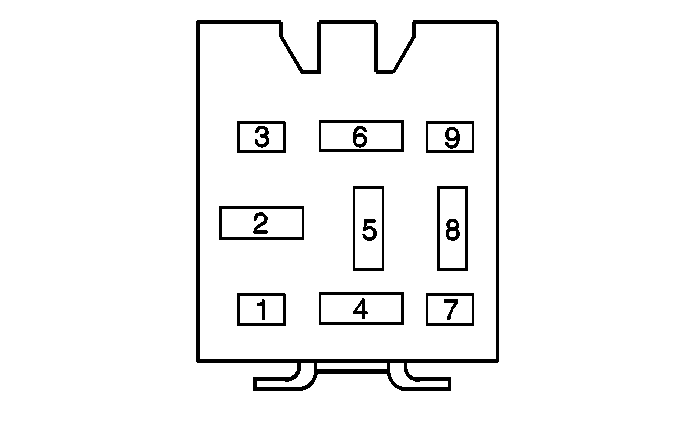
| |||||||
|---|---|---|---|---|---|---|---|
Connector Part Information |
| ||||||
Pin | Wire Color | Circuit No. | Function | ||||
1 | -- | -- | Not Used | ||||
2 | BRN | X100 | Fused Ignition Feed for High Side of Relay Coil | ||||
3 | -- | -- | Not Used | ||||
4 | GRN | U2 | Battery Feed to Compressor Clutch Coil | ||||
5 | -- | -- | Not Used | ||||
6 | YEL/BLU BRN/PPL | BP1 XY107 | A/C Cut Out to Heater and A/C Control A/C Compresssor Relay Control to ECM | ||||
7 | -- | -- | Not Used | ||||
8 | RED | A2 | Fused Battery Feed | ||||
9 | -- | -- | Not Used | ||||
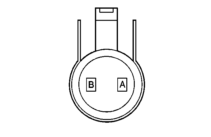
| |||||||
|---|---|---|---|---|---|---|---|
Connector Part Information |
| ||||||
Pin | Wire Color | Circuit No. | Function | ||||
A | BLK/BLU | FP99 | A/C Load Output Signal | ||||
B | BRN | X200 | Fused Ignition Feed | ||||
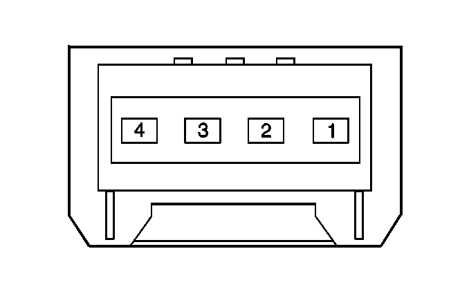
| |||||||
|---|---|---|---|---|---|---|---|
Connector Part Information |
| ||||||
Pin | Wire Color | Circuit No. | Function | ||||
1 | BLK/WHT | FM99 | A/C Request Signal to ECM | ||||
2 | BLK/WHT | FM7 | A/C Request Signal from Heater and A/C Control | ||||
3 | BRN/WHT | XM120 | Fused Ignition Feed from Relay K28 | ||||
4 | BLK | F57 | Switch Ground | ||||
| |||||||
|---|---|---|---|---|---|---|---|
Connector Part Information |
| ||||||
Pin | Wire Color | Circuit No. | Function | ||||
A | BLU/WHT | PM4 | 5 V Reference | ||||
B | BLU | P11 | Sensor Ground | ||||
| |||||||
|---|---|---|---|---|---|---|---|
Connector Part Information |
| ||||||
Pin | Wire Color | Circuit No. | Function | ||||
1 | BRN | X812 | 5 V Reference | ||||
2 | BLK/WHT | FM60 | Sun Sensor Signal | ||||
3 | BLK | F830 | Twilight Sensor Signal | ||||
4 | BLU | P111 | Sensor Ground | ||||

| |||||||
|---|---|---|---|---|---|---|---|
Connector Part Information |
| ||||||
Pin | Wire Color | Circuit No. | Function | ||||
1 | -- | -- | Not Used | ||||
2 | BLK | F830 | Twilight Sensor Input Signal | ||||
3 | BLK/WHT | FM60 | Sun Sensor Input Signal | ||||
4 | BRN/BLU | XP33 | Twilight Voltage Output Signal | ||||
5 | BLU | P111 P11 | Solar/Twilight and Outside Temp Sensor Ground | ||||
6 | BLK/WHT | FM11 | Fused Battery Voltage from Defogger Relay | ||||
7 | BRN | X812 | +5V Ref; Solar/Twilight Sensor | ||||
8 | GRY/GRN | RU502 | Fused Battery Voltage from Park Lamp Relay | ||||
9 | YEL/BLU | BP900 | A/C Compressor Relay Cutout Signal | ||||
10 | BLK/WHT | FM8 | A/C Request Output Signal | ||||
11 | BLK/BLU | FP812 | Blower Speed Output Signal | ||||
12 | BLU/WHT | PM4 | Outside Temp Sensor Input Signal | ||||
13 | BRN/WHT | XM112 | Blower Speed Input Signal | ||||
14 | BLK/WHT | FM14 | Rear Defog Switch Output Signal | ||||
15 | GRY/YEL | RB400 | Interior Lamps Dimming Input Signal | ||||
16 | -- | -- | Not Used | ||||
17 | BRN/WHT | XM110 | Serial Data (KW82) | ||||
18 | BLU/RED | PA400 | Vehicle Speed Input Signal from EBTCM | ||||
19 | BRN | X800 | Fused Ignition Feed | ||||
20 | GRN | U10 | RPM Input Signal | ||||
21 | BLK | F800 | Ground | ||||
22 | RED | A400 | Fused Battery Feed | ||||
| |||||||
|---|---|---|---|---|---|---|---|
Connector Part Information |
| ||||||
Pin | Wire Color | Circuit No. | Function | ||||
1 | WHT | 900 | LH Temp Valve Actuator Control (terminal 1) | ||||
2 | BLU | 901 | LH Temp Valve Actuator Control (terminal 3) | ||||
3 | BLK | 902 | LH Temp Valve Actuator Control (terminal 4) | ||||
4 | GRY | 903 | LH Temp Valve Actuator Control (terminal 6) | ||||
5 | WHT | 904 | RH Temp Valve Actuator Control (terminal 1) | ||||
6 | BLU | 905 | RH Temp Valve Actuator Control (terminal 3) | ||||
7 | BLK | 906 | RH Temp Valve Actuator Control (terminal 4) | ||||
8 | GRY | 907 | RH Temp Valve Actuator Control (terminal 6) | ||||
9 | WHT | 908 | Interior Air Valve Actuator Control (terminal 1) | ||||
10 | BLU | 909 | Interior Air Valve Actuator Control (terminal 3) | ||||
11 | BLK | 910 | Interior Air Valve Actuator Control (terminal 4) | ||||
12 | GRY | 911 | Interior Air Valve Actuator Control (terminal 6) | ||||
13 | WHT | 912 | Floor Air Valve Actuator Control (terminal 1) | ||||
14 | BLU | 913 | Floor Air Valve Actuator Control (terminal 3) | ||||
15 | BLK | 914 | Floor Air Valve Actuator Control (terminal 4) | ||||
16 | GRY | 915 | Floor Air Valve Actuator Control (terminal 6) | ||||
17 | WHT | 919 | Defrost Valve Actuator Control (terminal 1) | ||||
18 | BLU | 918 | Defrost Valve Actuator Control (terminal 3) | ||||
19 | BLK | 917 | Defrost Valve Actuator Control (terminal 4) | ||||
20 | GRY | 916 | Defrost Valve Actuator Control (terminal 6) | ||||
21 | BLU/WHT | 920 | Water Cutoff Vacuum Solenoid Valve Control | ||||
22 | BLU/BLK | 921 | Recirc Vacuum Solenoid Valve Control | ||||
23 | BRN/BLK | 922 | LH and RH Temp Sensor Ground | ||||
24 | GRN/RED | 923 | 5V Ref; LH Air Temp Sensor | ||||
25 | GRN/BRN | 924 | 5V Ref; RH Air Temp Sensor | ||||
26 | YEL | 925 | Battery Power Supply | ||||
| |||||||
|---|---|---|---|---|---|---|---|
Connector Part Information |
| ||||||
Pin | Wire Color | Circuit No. | Function | ||||
1 | RED | A465 | Fused Battery Feed | ||||
2 | BLK/BLU | FP812 | Blower Speed Input Signal | ||||
3 | BLK | F812 | Ground | ||||
4 | BRN/WHT | XM112 | Blower Speed Output Signal | ||||
5 | -- | -- | Not Used | ||||
| |||||||
|---|---|---|---|---|---|---|---|
Connector Part Information |
| ||||||
Pin | Wire Color | Circuit No. | Function | ||||
1 | WHT | 919 | Stepper Motor Coil 1 Control | ||||
2 | YEL | 936 | Battery Feed | ||||
3 | BLU | 918 | Stepper Motor Coil 2 Control | ||||
4 | BLK | 917 | Stepper Motor Coil 4 Control | ||||
5 | YEL | 937 | Battery Feed | ||||
6 | GRY | 916 | Stepper Motor Coil 3 Control | ||||

| |||||||
|---|---|---|---|---|---|---|---|
Connector Part Information |
| ||||||
Pin | Wire Color | Circuit No. | Function | ||||
1 | WHT | 912 | Stepper Motor Coil 1 Control | ||||
2 | YEL | 934 | Battery Feed | ||||
3 | BLU | 913 | Stepper Motor Coil 2 Control | ||||
4 | BLK | 914 | Stepper Motor Coil 4 Control | ||||
5 | YEL | 935 | Battery Feed | ||||
6 | GRY | 915 | Stepper Motor Coil 3 Control | ||||

| |||||||
|---|---|---|---|---|---|---|---|
Connector Part Information |
| ||||||
Pin | Wire Color | Circuit No. | Function | ||||
1 | WHT | 908 | Stepper Motor Coil 1 Control | ||||
2 | YEL | 932 | Battery Feed | ||||
3 | BLU | 909 | Stepper Motor Coil 2 Control | ||||
4 | BLK | 910 | Stepper Motor Coil 4 Control | ||||
5 | YEL | 933 | Battery Feed | ||||
6 | GRY | 911 | Stepper Motor Coil 3 Control | ||||

| |||||||
|---|---|---|---|---|---|---|---|
Connector Part Information |
| ||||||
Pin | Wire Color | Circuit No. | Function | ||||
1 | WHT | 900 | Stepper Motor Coil 1 Control | ||||
2 | YEL | 929 | Battery Feed | ||||
3 | BLU | 901 | Stepper Motor Coil 2 Control | ||||
4 | BLK | 902 | Stepper Motor Coil 4 Control | ||||
5 | YEL | 928 | Battery Feed | ||||
6 | GRY | 903 | Stepper Motor Coil 3 Control | ||||

| |||||||
|---|---|---|---|---|---|---|---|
Connector Part Information |
| ||||||
Pin | Wire Color | Circuit No. | Function | ||||
1 | WHT | 904 | Stepper Motor Coil 1 Control | ||||
2 | YEL | 930 | Battery Feed | ||||
3 | BLU | 905 | Stepper Motor Coil 2 Control | ||||
4 | BLK | 906 | Stepper Motor Coil 4 Control | ||||
5 | YEL | 931 | Battery Feed | ||||
6 | GRY | 907 | Stepper Motor Coil 3 Control | ||||
