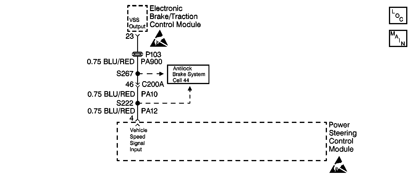
Circuit Description
The electronic brake/traction control module (EBTCM), transmits a processed vehicle speed signal (VSS) from terminal 23 to terminal 4 of the power steering control module (PSCM). The PSCM uses the speed signal and the characteristic curve programmed in the microprocessor to determine the electric current variable for the power steering fluid flow control valve actuator.
Conditions for Setting the DTC
The power steering control module detects that the speed signal is no longer present at terminal 4.
Action Taken When the DTC Sets
| • | Power steering assist will default to partial manual steering. |
| • | The PSCM will store a DTC 21 in memory. |
Conditions for Clearing the DTC
| • | Conditions for the fault are no longer present. |
| • | Using the scan tool. |
Diagnostic Aids
Check for the following conditions if a history or intermittent DTC is indicated:
| • | A poor connection at the PSCM. Inspect the harness connectors for backed out terminals, improper mating, improperly formed or damaged terminals, and poor terminal to wire connections. |
| • | A damaged wiring harness. Inspect the wiring harness for damage. If the wiring harness appears to be in good condition, observe the display on the DMM while moving the connectors and wiring harnesses related to the circuits. A change in the DMM display during this test will indicate the location of the fault. |
| • | For additional information, refer to Intermittents and Poor Connections Diagnosis |
Test Description
The number(s) below refer to the step number(s) on the diagnostic table.
-
This step checks to see if the speedometer is operating properly.
-
This step checks for the speed signal input into the power steering control module.
-
This step replaces the power steering control module.
Step | Action | Value(s) | Yes | No |
|---|---|---|---|---|
1 | Was the Variable Effort Steering System Check performed? | -- | ||
Does the speedometer operate properly? | -- | Go to Speedometer and/or Odometer Inoperative in I/P, Guages and Console. | ||
Is the measured voltage within the specified value? | Greater than 1 VAC | |||
4 |
Is the repair complete? | -- | -- | |
Replace the power steering control module. Refer to Power Steering Control Module Replacement Is the replacement complete? | -- | -- | ||
6 |
Is DTC 21 present? | -- | System OK |
