Circuit Description
The inflatable restraint Sensing and Diagnostic and Seat Belt Pretensioner
Module (SDM) performs TURN-ON tests to diagnose critical malfunctions within
itself when the ignition switch is turned ON. The SDM monitors the six firing
loops to detect leakage currents to ground and system voltage in the frontal
and side air bag inflator module and seat belt pretensioner circuits. Then,
the SDM proceeds with the RESISTANCE MEASUREMENT test to measure the deployment
loop resistances to ensure they are within their respective normal resistance
ranges. Upon passing these tests, and if the energy reserve is charged up,
the firing transistors are tested. The SDM then goes into CONTINUOUS MONITORING
mode. The SDM service wait time is 1 minute. Refer to On-Vehicle Service
for enable/disable procedures.
Conditions for Setting the DTC
| • | The ignition is within normal operating voltage range. |
| • | The measured leakage currents to system voltage in the inflatable
restraint steering wheel module deployment loop are above a specified value
caused by a short circuit between the driver frontal air bag deployment
loop and system voltage. |
DTC 15 will set once one of these conditions is met. This test
is run during the SDM Turn-ON tests.
Action Taken When the DTC Sets
| • | The SDM sets a Diagnostic Trouble Code. |
| • | The SDM turns ON the AIR BAG warning lamp. |
Conditions for Clearing the DTC
Current and History DTC codes must be cleared using a scan tool Clear
DTC Information command. If the circuit fault has been successfully repaired
and the conditions which caused the Current DTC 15 to set are no
longer existing, History DTC 15 will set. History DTC 15 may
be cleared using the scan tool.
Diagnostic Aids
A short circuit to a voltage source in the inflatable restraint steering
wheel module circuit or a short circuit between the communication signal line
of the LH or RH inflatable restraint Side Impact Sensor can set this DTC.
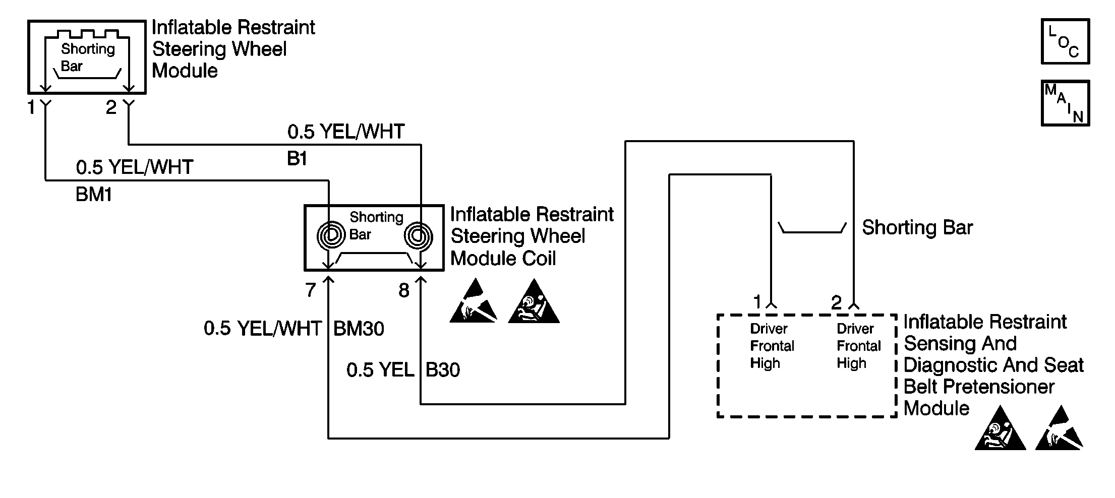
Inspect CKTs BM30 and B30 carefully for cutting and/or chafing.
| • | If DTC 15 and DTC 73 are set, inspect CKTs BM30,
B30 and B41 carefully for cutting and/or chafing. |
| • | If DTC 15 and DTC 83 are set, inspect CKTs BM30,
B30 and M44 carefully for cutting and/or chafing. |
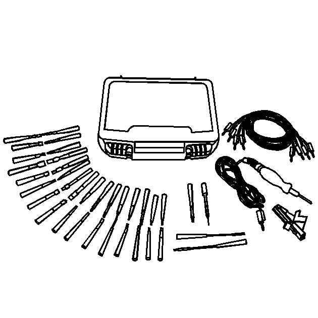
When measurements are requested in this table, use J 39200
Digital Multimeter with
the correct terminal adapter from J 35616
Connector Test Adapter Kit. When a check for proper connection
is requested, refer to
Intermittents and Poor Connections
. When a wire, connector or terminal repair is
requested, use J-38125
Terminal Repair Kit and refer to
Wiring Repair
.
Test Description
The numbers below refer to step numbers on the diagnostic table.
-
This
test determines whether the malfunction is in inflatable restraint steering
wheel module.
-
This test determines whether the malfunction is in the
inflatable restraint steering wheel module coil.
-
This test determines
whether the malfunction is in CKT BM30.
-
This test determines
whether the malfunction is in CKT B30.
DTC 15 Driver Air Bag Deploy. Loop Short to B+
--
| Action
| Value(s)
| Yes
| No
|
1
| Was the SIR Diagnostic System Check
performed?
| --
|
Go to Step 2
| Go to
SIR Diagnostic System Check
|
2
|
- Turn the ignition switch to the OFF position.
- Wait one minute until the SDM energy reserve capacitors have discharged.
- Disconnect the negative battery cable. Refer to
Caution: Unless directed otherwise, the ignition and start switch must be in the OFF or LOCK position, and all electrical loads must be OFF before servicing
any electrical component. Disconnect the negative battery cable to prevent an electrical spark should a tool or equipment come in contact with an exposed electrical terminal. Failure to follow these precautions may result in personal injury and/or damage to
the vehicle or its components.
.
- Disconnect the inflatable restraint steering wheel module. Refer
to
Steering Wheel Inflator Module Replacement
in Steering Wheel and Column--Tilt.
- Use the J 38715-30 adapter to connect the J 38715-A
SIR Driver/Passenger Load Tool STEERING
COLUMN connector to the inflatable restraint steering wheel module integral
harness connector.
- Reconnect the negative battery cable.
- Turn the ignition switch to the ON position.
- Use the scan tool to request the SIR diagnostic trouble code display.
Is DTC 15 still current?
| --
|
Go to Step
4
|
Go to Step 3
|
3
|
- Turn the ignition switch to the OFF position.
- Inspect the inflatable restraint steering wheel module integral
harness connector for damage.
- Ensure the nearby wiring is routed correctly.
- Replace the inflatable restraint steering wheel module. Refer
to
Steering Wheel Inflator Module Replacement
in Steering Wheel and Column--Tilt.
Are the repairs complete?
| --
|
Go to Step
15
| --
|
4
|
- Turn the ignition switch to the OFF position.
- Wait one minute until the SDM energy reserve capacitors have discharged.
- Disconnect the negative battery cable. Refer to
Caution: Unless directed otherwise, the ignition and start switch must be in the OFF or LOCK position, and all electrical loads must be OFF before servicing
any electrical component. Disconnect the negative battery cable to prevent an electrical spark should a tool or equipment come in contact with an exposed electrical terminal. Failure to follow these precautions may result in personal injury and/or damage to
the vehicle or its components.
.
- Disconnect the inflatable restraint steering wheel module coil
wiring harness connector. Refer to
Steering Wheel Inflator Module Coil Replacement
in Steering Wheel
and Column--Tilt.
- Use the J 38715-40 adapter to connect the J 38715-A
SIR Driver/Passenger Load Tool BASE
OF COLUMN connector to the inflatable restraint steering wheel module coil
connector at the top of the steering column.
- Reconnect the negative battery cable.
- Turn the ignition switch to the ON position.
- Use the scan tool to request the SIR diagnostic trouble code display.
Is DTC 15 still current?
| --
|
Go to Step
6
|
Go to Step 5
|
5
|
- Turn the ignition switch to the OFF position.
- Remove the inflatable restraint steering wheel module coil. Refer
to
Steering Wheel Inflator Module Coil Replacement
in Steering Wheel and Column--Tilt.
- Remove the connecting wires.
- Inspect the inflatable restraint steering wheel module coil for
damage.
- Inspect the connecting wires for damage.
- Determine the cause of damage.
- Repair the cause of the damage.
- Replace the inflatable restraint steering wheel module coil. Refer
to
Steering Wheel Inflator Module Coil Replacement
in Steering Wheel and Column--Tilt.
Are the repairs complete?
| --
|
Go to Step
15
| --
|
6
|
- Turn the ignition switch to the OFF position.
- Wait one minute until the SDM energy reserve capacitors have discharged.
- Disconnect the negative battery cable. Refer to
Caution: Unless directed otherwise, the ignition and start switch must be in the OFF or LOCK position, and all electrical loads must be OFF before servicing
any electrical component. Disconnect the negative battery cable to prevent an electrical spark should a tool or equipment come in contact with an exposed electrical terminal. Failure to follow these precautions may result in personal injury and/or damage to
the vehicle or its components.
.
- Disconnect the inflatable restraint Sensing and Diagnostic and
Seat Belt Pretensioner Module (SDM). Refer to
Inflatable Restraint Sensing and Diagnostic and Seat Belt Pretensioner Module Replacement
.
- Check for proper connection at terminals 1 and 2 on the SDM harness
connector.
Are the terminals damaged or corroded?
| --
|
Go to Step 7
|
Go to Step
9
|
7
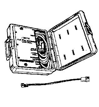
| Use the J 42250 Catera Terminal Repair Kit to repair
the SDM harness connector.
Are the repairs complete?
| --
|
Go to Step
8
| --
|
8
| Check for proper connection at terminals 1 and 2 on the SDM.
Are the terminals damaged or corroded?
| --
|
Go to Step 10
|
Go to Step
15
|
9
| Check for proper connection at terminals 1 and 2 on the
SDM.
Are the terminals damaged or corroded?
| --
|
Go to Step
10
|
Go to Step 11
|
10
| Replace the inflatable restraint Sensing and Diagnostic and Seat Belt
Pretensioner Module (SDM). Refer to
Inflatable Restraint Sensing and Diagnostic and Seat Belt Pretensioner Module Replacement
.
Are the repairs complete?
| --
|
Go to Step
15
| --
|
11
|
- Disconnect the J 38715-A
SIR Driver/Passenger Load Tool.
- Insert the J 42113
Shorting Bar Tool into the SDM harness connector terminal above terminals
1 and 2. This opens the short circuit bridge between terminals 1 and 2.
- Reconnect the negative battery cable.
- Turn the ignition switch to the ON position.
- Use the J 39200
Digital
Multimeter to measure the voltage on the SDM harness connector from terminal 1
to terminal 7 (ground).
Is the measured voltage less than the specified value?
| 1 V
|
Go to Step 13
|
Go to Step 12
|
12
|
- Turn the ignition switch to the OFF position.
- Repair a short to B+ condition in CKT BM30.
Is the repair complete?
| --
|
Go to Step
15
| --
|
13
| Measure the voltage on the SDM harness connector from terminal 2 to
terminal 7 (ground).
Is the measured voltage less than the specified value?
| 1 V
| Go to
Integrity Check
|
Go to Step
14
|
14
|
- Turn the ignition switch to the OFF position.
- Repair a short to B+ condition in CKT B30.
Is the repair complete?
| --
|
Go to Step
15
| --
|
15
| Reconnect all the SIR system components. Ensure all the SIR system components
are properly mounted.
Are all the SIR system components reconnected and are all the SIR system
components properly mounted?
| --
|
Go to Step
16
| --
|
16
| Clear the SIR diagnostic trouble codes.
Are the SIR diagnostic trouble codes cleared?
| --
| Go to
SIR Diagnostic System Check
| --
|
