Removal Procedure
Tools Required
| • | J 42066 Wheel Hub Flange Holding Adapter |
| • | J 42071 Drive Axle Separator |
- Place the gear selector in the NEUTRAL position.
- Raise and support the vehicle. Refer to Lifting and Jacking the Vehicle in General Information.
- Remove the tire and wheel assembly. Refer to Wheel Removal .
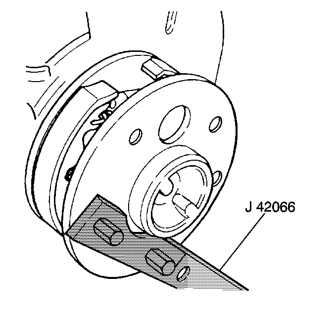
- Install the J 42066 to the wheel hub flange with the wheel bolts.
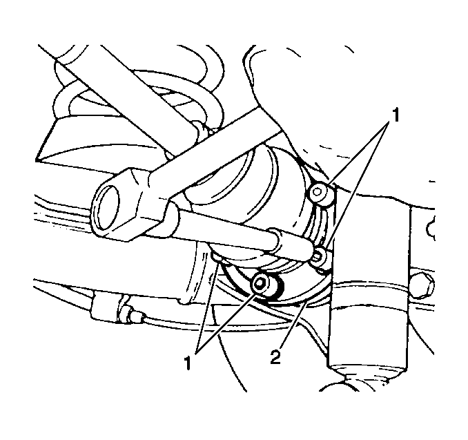
- Remove the bolts from the drive axle flange while holding the J 42066 with a ratchet.
- Separate the outer end of the drive axle from the wheel bearing hub inner flange.
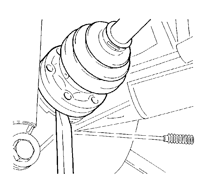
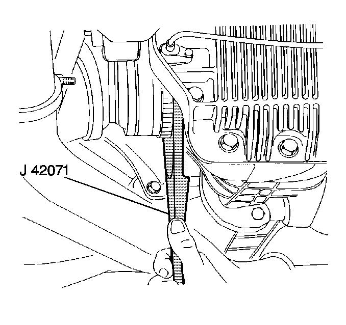
- Use the J 42071 and a deadblow hammer to separate the drive axle from the rear axle differential.
- Remove the drive axle from the vehicle.
- Clean the drive axle spline.
- Clean the seal surfaces.


Important: Ensure that the beveled side of the J 42071 , labeled Differential Side, is against the differential and not against the drive axle or damage to the ABS sensor reluctor ring may occur.
Installation Procedure
- Lubricate the drive axle spline with differential lubricant.
- Lubricate the seal surfaces with differential lubricant.
- Use a rubber faced mallet to drive the outer end of the drive axle to install the drive axle into the differential bore.
- Position the other end of the drive axle into the wheel bearing hub inner flange.
- Use a ratchet to hold the J 42066 while installing the bolts (1) to the drive axle flange (2).
- Remove the J 42066 from the wheel hub flange.
- Install the tire and wheel assembly. Refer to Wheel Installation .
- Lower the vehicle.
Important: Use only enough force necessary to seat the drive axle into the rear axle differential.

Notice: Use the correct fastener in the correct location. Replacement fasteners must be the correct part number for that application. Fasteners requiring replacement or fasteners requiring the use of thread locking compound or sealant are identified in the service procedure. Do not use paints, lubricants, or corrosion inhibitors on fasteners or fastener joint surfaces unless specified. These coatings affect fastener torque and joint clamping force and may damage the fastener. Use the correct tightening sequence and specifications when installing fasteners in order to avoid damage to parts and systems.
Tighten
Tighten the bolts to 50 N·m (37 lb ft) +
67°.
