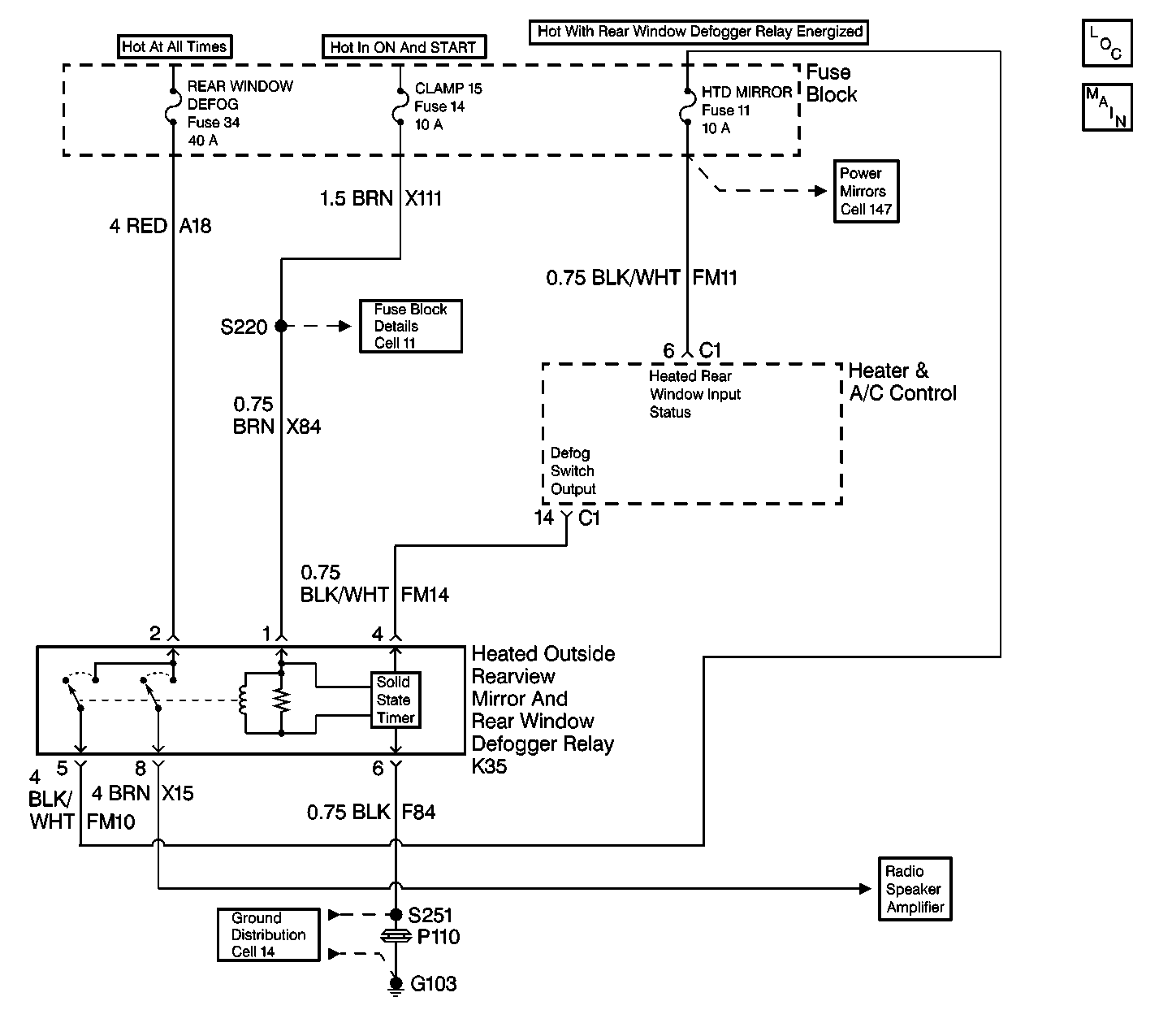
Circuit Description
The rear defogger switch is a momentary switch that returns to the rest position after it is pressed to the ON or OFF positions. When it is pressed to the ON position, with the engine running, it supplies voltage to the internal timer relay coil. With voltage supplied, and ground provided, the internal timer relay energizes, and closes the relay contacts. With the contacts closed, voltage is supplied to the radio antenna amplifier which routes the voltage to the rear defogger grid. Voltage is also supplied to the heated outside rear view mirrors through the HTD MIRROR fuse. With voltage supplied and ground provided to the defogger grid and outside mirrors, the grid and outside mirrors begins to warm and the defogger switch light emitting diode (LED) turns ON.
Approximately fifteen minutes after the defogger switch is pressed to the ON position, the internal timer relay shuts off. This open the relay contacts, and terminates the voltage source to the defogger grid and outside mirrors. The rear window and outside mirror glass begins to cool.
The rear defogger operation can also be shut off at anytime before the fifteen minute time period expires, by pressing the rear defogger switch to the OFF position.
In addition to the rear defogger and outside mirrors receiving voltage, the heater and A/C control also receives a voltage signal (feedback) at terminal 6 (C1). Whenever a rear defog request is made, with the engine running, a voltage output signal is sent to the rear defogger relay, the heater and A/C control checks this signal (feedback) before and after the signal is sent. The heater and A/C control looks for the feedback signal to change from a LO state to a HI (B+) state. This indicates that the signal was sent and the relay energized completing the circuit to the heater and A/C control.
Conditions for Setting the DTC
| • | Circuit FM14 is tested every 40 ms with the ignition switch in the ON position and the rear defogger active. |
| • | A DTC 33 indicates that CKT FM14 is shorted to battery. |
Action Taken When the DTC Sets
| • | The heater and A/C controller stores a DTC 33 in memory. |
| • | DTC 34 may also be present and is normal. |
| • | The controller internally does not disable the voltage output. |
Conditions for Clearing the DTC
| • | The condition for the fault is no longer present. |
| • | Using a scan tool. |
| • | A history DTC will clear after 20 consecutive ignition cycles if the condition for the fault is no longer present. |
Diagnostic Aids
| • | If DTC 34 is present, repair DTC 33 first. After the repair is made, recheck for DTC 34 and repair as needed if present. |
| • | If the DTC is a history or an intermittent. Try to perform the tests shown while moving wiring harnesses and connectors, this can often cause the malfunction to appear. |
| • | When moving related harnesses and harness connectors, visually/physically inspect wiring and connectors for the following: |
| • | Wiring broken inside the insulation. |
| • | Poor mating of the connector halves or a terminal not fully seated in the connector body (backed out). |
| • | Improperly formed or damaged terminals. All connector terminals in the related circuits should be carefully reformed or replaced to insure proper contact tension. |
| • | Poor terminal to wire connection. Inspect for poor crimps, crimping over wire insulation rather than contact tension. |
| • | Check the power and ground circuits before replacing the heater and A/C control. |
Test Description
The numbers below refer to the step numbers on the diagnostic table.
-
Determines if the voltage signal is being sent by the heater and A/C control and the circuit being complete.
-
This test double checks if an open circuit exists in FM14.
-
Determines if a short to battery exists with the ignition ON or OFF.
-
Replace the relay before condemning the heater and A/C control.
Step | Action | Value(s) | Yes | No |
|---|---|---|---|---|
1 | Was the Defogger System Check performed? | -- | Go to Defogger System Check | |
Is the voltage within the specified value? | B+ | |||
3 |
Is the resistance within the specified value? | 0-5ohms | ||
Is the resistance within the specified value? | 0-5ohms | |||
Are both voltage readings within the specified range? | Less than 0.1 V | |||
6 | Locate and repair the open ground circuit. Is the repair complete? | -- | -- | |
7 | Locate and repair the open circuit in CKT FM14. Is the repair complete? | -- | -- | |
Replace the rear defogger relay (K35). Is the replacement complete? | -- | -- | ||
9 | Locate and repair the short to B+ in CKT FM14. Is the repair complete? | -- | -- | |
10 |
Is a current DTC 33 present? | -- | Go to Defogger System Check | |
11 | Replace and program the heater and A/C control. Refer to Heater and A/C Control Replacement for the programming procedure. Is the replacement and programming complete? | -- | Go to Defogger System Check | -- |
