Air Conditioning (A/C) Temperature Sensor Replacement Drivers Side
Removal Procedure
Caution: This vehicle is equipped with a Supplemental Inflatable Restraint (SIR) System. Failure to follow the correct procedure could cause the following conditions:
• Air bag deployment • Personal injury • Unnecessary SIR system repairs • Refer to SIR Component Views in order to determine if you are performing service on or near the SIR components or the SIR wiring. • If you are performing service on or near the SIR components or the SIR wiring, disable the SIR system. Refer to Disabling the SIR System.
- Disconnect the left (driver) side sound insulator positive locking tabs.
- Remove the sound insulator.
- Disconnect the left (driver) side front floor air outlet fastening clip.
- Remove the front floor air outlet.
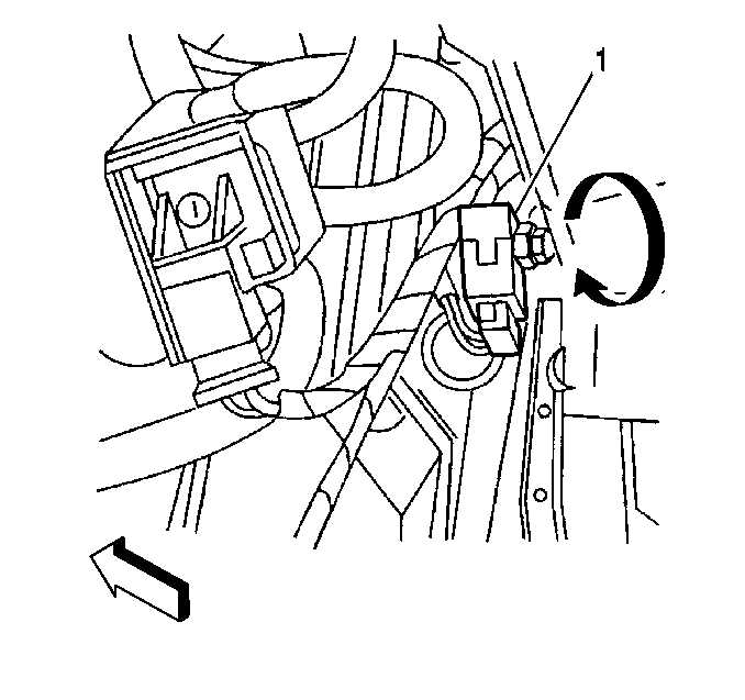
- Turn the temperature sensor (1) 180 degrees.
- Carefully remove the temperature sensor from the air distribution module.
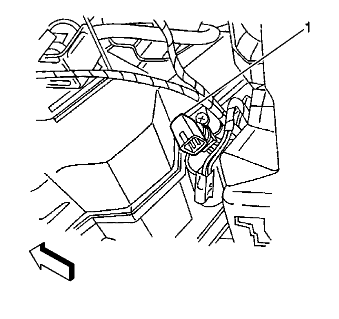
- Disconnect the electrical connection (1) from the temperature sensor.


Installation Procedure
- Connect the electrical connection (1) to the temperature sensor.
- Carefully insert the temperature sensor into the air distribution module.
- Turn the temperature sensor (1) 180 degrees.
- Install the left (driver) side front floor air outlet.
- Connect the air outlet fastening clip.
- Install the left (driver) side sound insulator.
- Connect the sound insulator positive locking tabs.


Air Conditioning (A/C) Temperature Sensor Replacement Passenger Side
Removal Procedure
Caution: This vehicle is equipped with a Supplemental Inflatable Restraint (SIR) System. Failure to follow the correct procedure could cause the following conditions:
• Air bag deployment • Personal injury • Unnecessary SIR system repairs • Refer to SIR Component Views in order to determine if you are performing service on or near the SIR components or the SIR wiring. • If you are performing service on or near the SIR components or the SIR wiring, disable the SIR system. Refer to Disabling the SIR System.
- Disconnect the right (passenger) side sound insulator positive locking tabs.
- Remove the sound insulator.
- Disconnect the right (passenger) side front floor air outlet fastening clip.
- Remove the front floor air outlet.
- Remove the mode valve (floor) actuator. Refer to Mode Actuator Replacement .
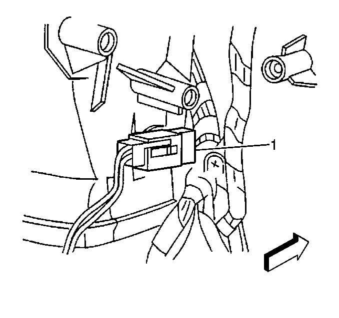
- Turn the temperature sensor (1) 180 degrees.
- Carefully remove the temperature sensor from the air distribution module.
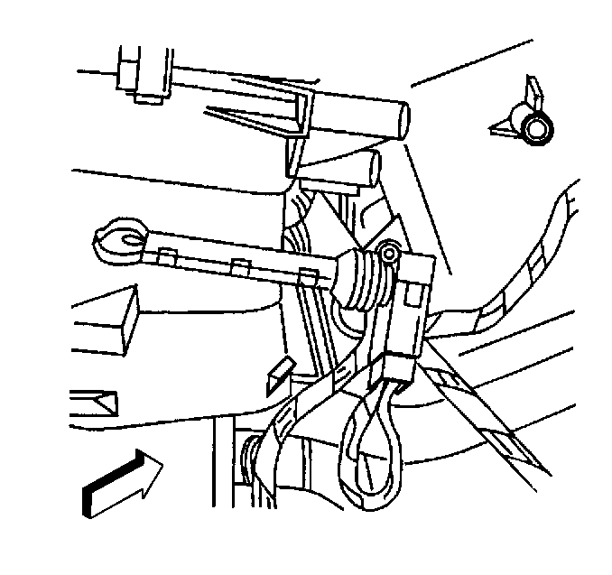
- Disconnect the electrical connection from the temperature sensor.


Installation Procedure
- Connect the electrical connection to the temperature sensor.
- Carefully insert the temperature sensor into the air distribution module.
- Turn the temperature sensor (1) 180 degrees.
- Ensure the electrical connector is positioned horizontally.
- Install the mode valve (floor) actuator. Refer to Mode Actuator Replacement .
- Install the right (passenger) side front floor air outlet.
- Connect the front floor air outlet fastening clip.
- Install the right (passenger) side sound insulator.
- Connect the sound insulator positive locking tabs.


