Removal Procedure
- Remove the driver side instrument panel sound insulator. Refer to Instrument Panel Insulator Replacement in Instrument Panel, Gages and Console.
- Remove the driver side front floor air outlet duct. Refer to Floor Air Outlet Duct Replacement in Instrument Panel, Gages and Console.
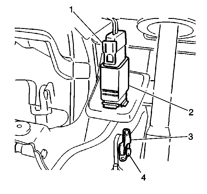
- Remove the brake pedal pivot pin retainer (3) from the brake pedal pivot pin (4).
- Remove the brake pedal pivot pin from the power brake booster pushrod clevis.
- Remove the wiring harness connector (1) from the stoplamp switch (2).
- Use angle pointed pliers to compress both the locking tabs to remove the stoplamp switch.
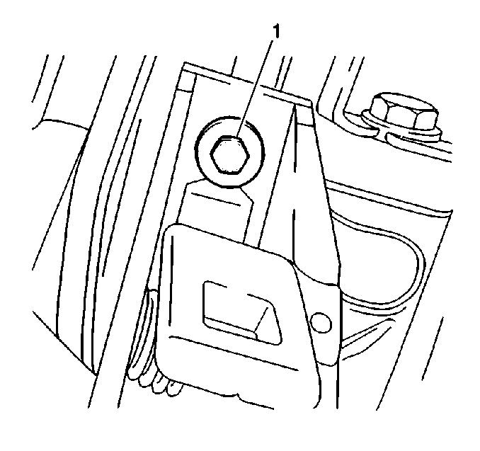
- Remove the brake pedal bracket bolt (1) from the brake pedal bracket.
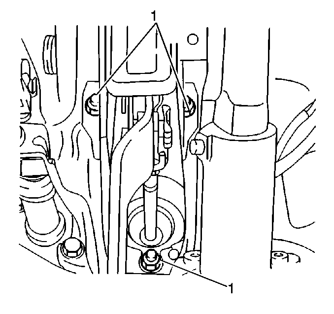
- Remove the brake pedal bracket nuts (1) from the brake pedal bracket at the dash panel.
- Pull the power brake booster slightly away from the underhood mounting surface.
- Swing the brake pedal bracket backwards to remove.


Installation Procedure
- Install the brake pedal bracket into the mounting position.
- Re-seat the power brake booster.
- Install the brake pedal bracket nuts (1) to the brake pedal bracket at the dash panel.
- Install the brake pedal bracket bolt (1) to the brake pedal bracket.
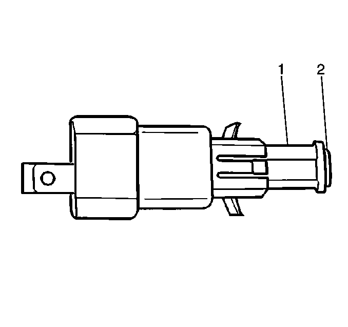
- Pull both the actuating pin (2) and the retaining collar (1) out of the stoplamp switch to the full extended position of about 17 mm (0.66 in).
- Engage the tangs on the stoplamp switch with the pedal bracket to install the stoplamp switch to the brake pedal bracket.
- Install the wiring harness connector (1) to the stoplamp switch (2).
- Remove the brake pedal pivot pin through the pedal arm and into the pushrod clevis.
- Remove the brake pedal pivot pin retainer (3) to the brake pedal pivot pin (4).
- Remove the driver side front floor air outlet duct. Refer to Floor Air Outlet Duct Replacement in Instrument Panel, Gages and Console.
- Remove the driver side instrument panel sound insulator. Refer to Instrument Panel Insulator Replacement in Instrument Panel, Gages and Console.

Tighten
Tighten the brake pedal bracket nuts (1) to 20 N·m (15 lb ft).
Refer to
Notice: Use the correct fastener in the correct location. Replacement fasteners must be the correct part number for that application. Fasteners requiring replacement or fasteners requiring the use of thread locking compound or sealant are identified in the service procedure. Do not use paints, lubricants, or corrosion inhibitors on fasteners or fastener joint surfaces unless specified. These coatings affect fastener torque and joint clamping force and may damage the fastener. Use the correct tightening sequence and specifications when installing fasteners in order to avoid damage to parts and systems.
in General Information.
Tighten
Tighten the brake pedal bracket bolt (1) to 20 N·m (15 lb ft).


Important: Do not push the actuating pin into the stoplamp switch. The actuating pin self-adjusts to the brake pedal position when the brake pedal returns to the at-rest position.
