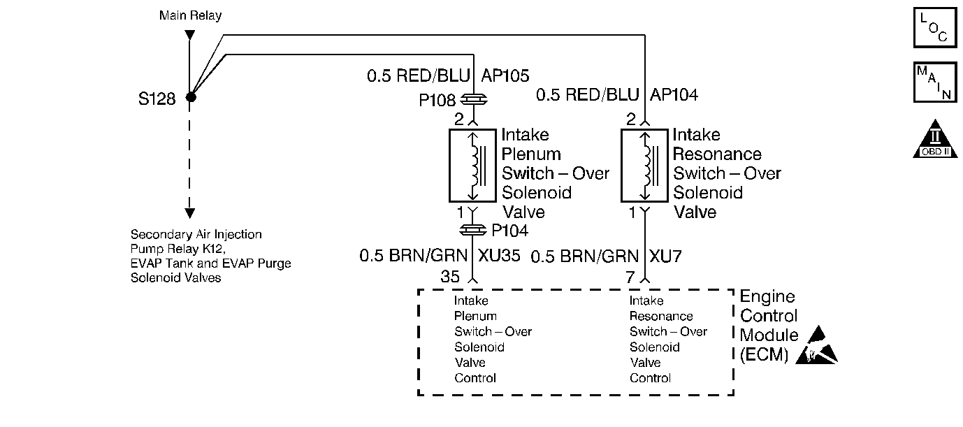
Circuit Description
The Catera Multi-Ram System uses variable air induction tuning in order to achieve maximum performance and efficiency over the entire operating range of the engine. The system consists of two main parts. The intake manifold contains the Intake Plenum Switchover valve. This vacuum operated valve is essentially a moveable divider that changes the airflow characteristics of the intake manifold. Vacuum to the valve is controlled by an ECM controlled solenoid valve. The second part is the Intake Resonance Switchover valve. This vacuum operated valve is located in the air intake duct assembly in front of the engine. This is also basically a moveable divider that changes the tuning of the air intake system. Vacuum to the valve is controlled by an ECM controlled solenoid valve. By opening and closing these valves independently, in different combinations, four different air flow configurations can be created, each optimized to a particular set of engine operating conditions.
Both solenoid valves are supplied power via the Main relay (Switched B+). Both solenoid valves have a control circuit to the Engine Control Module (ECM). The ECM controls a valve by grounding the control circuit via an internal solid state device called a driver. The primary function of the driver is to supply the ground for the component being controlled. Each driver has a fault line which is monitored by the ECM. When the ECM is commanding a component on, the voltage of the control circuit should be low (near 0 volts). When the ECM is commanding the control circuit to a component off, the voltage potential of the circuit should be high (near the battery voltage). If a problem is detected with either of the solenoid valve control circuits, a DTC will set. If either of the following DTCs are set, perform the DTC table before running this diagnostic:
| • | DTC P1112 -- Intake Plenum Switchover Valve Control |
| • | DTC P1113 -- Intake Resonance Switchover Valve Control |
Diagnostic Aids
Visually inspect the system. Check and repair the following conditions as necessary:
| • | Check for any disconnected or damaged vacuum hoses/components. |
| • | Check the linkage between the vacuum actuators and the valves. Move the linkage by hand. Check for binding, or any interference with the hoses, the wiring or any other components. |
Test Description
The number(s) below refer to step numbers on the diagnostic table.
Multi-Ram System Diagnosis
Step | Action | Value(s) | Yes | No | ||||
|---|---|---|---|---|---|---|---|---|
1 | Did you perform the Powertrain On-Board Diagnostic (OBD) System Check? | -- | ||||||
Is DTC P1112 or P1113 set? | -- | Go to the applicable DTC | ||||||
3 |
Was a problem found? | -- | ||||||
4 |
Do both valves operate? | -- | ||||||
5 |
Do both valves operate properly? | -- | No trouble found | |||||
6 | The remainder of the table applies to the valve(s) that did not operate.
Does the actuator move when the vacuum is disconnected? | -- | ||||||
7 | Is a vacuum present on the manifold vacuum supply hose? | -- | ||||||
8 | Disconnect the other hose from the solenoid valve. Then, connect the hoses together by using a suitable vacuum connector. Does the actuator linkage operate? | -- | ||||||
9 | Disconnect the vacuum hose from the actuator. Is a vacuum present? | -- | ||||||
10 | Replace the solenoid valve. Is the action complete? | -- | -- | |||||
11 | Repair the vacuum supply hose or the plugged vacuum source. Is the action complete? | -- | -- | |||||
12 | Repair the vacuum hose to the actuator. Is the action complete? | -- | -- | |||||
13 | Replace the valve/actuator assembly. Is the action complete? | -- | -- | |||||
14 | Replace the affected valve/actuator assembly. Is the action complete? | -- | -- | |||||
15 |
Do both valves operate? | -- | The System is OK |
