Exhaust Manifold Replacement Driver Side
Removal Procedure
- Remove the engine assembly. Refer to Engine Replacement .
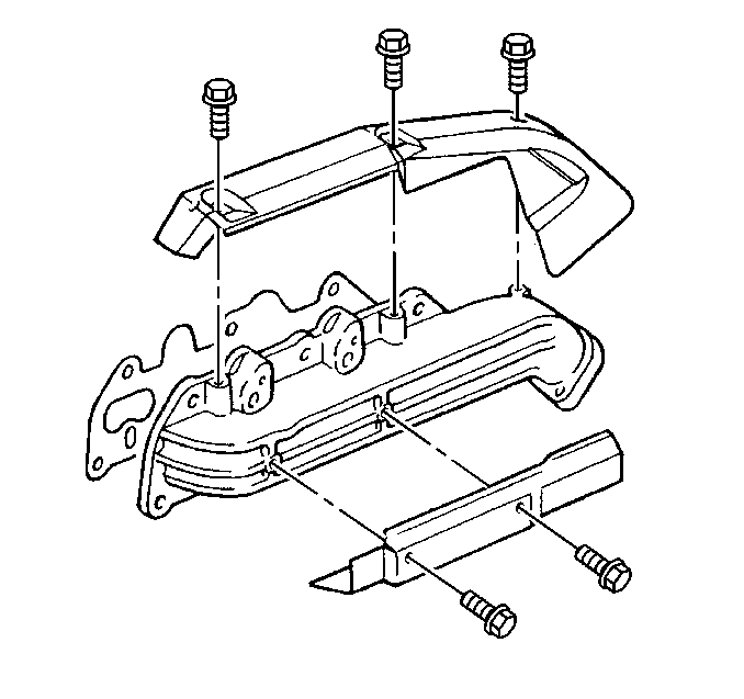
- Remove the exhaust manifold lower heat shield bolts.
- Remove the exhaust manifold lower heat shield.
- Remove the exhaust manifold upper heat shield bolts.
- Remove the exhaust manifold upper heat shield.
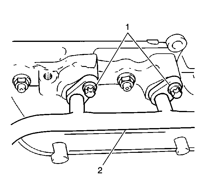
- Remove the AIR injection pipe bolts (1).
- Pull the AIR injection pipe (2) away from the exhaust manifold to enable access to the fastening nuts from the manifold.
- Remove the AIR injection pipe from the exhaust manifold.
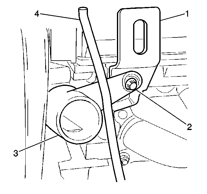
- Remove the coolant pipe (3) and the engine lift bracket bolt (2) from the cylinder head.
- Grasp the oil level indicator tube (4) firmly.
- Pull the oil level indicator tube upwards for removal.
- Remove the exhaust manifold fastening nuts.
- Clean the cylinder head mating surfaces.
- Clean the exhaust manifold mating surfaces.
Installation Procedure
- Install the exhaust manifold nuts.
- Install the oil level indicator tube (4).
- Install the coolant pipe (3) and the engine lift bracket bolt (2) to the cylinder head. Ensure the bolt passes through all of the attached components.
- Install the AIR injection pipe to the exhaust manifold.
- Coat the AIR injection pipe bolts with high temperature anti-seize compound, GM P/N 5613695 or equivalent.
- Install the AIR injection pipe bolts (1).
- Install the exhaust manifold upper heat shield.
- Coat the exhaust manifold upper heat shield bolts with high temperature anti-seize compound, GM P/N 5613695 or equivalent.
- Install the exhaust manifold upper heat shield bolts.
- Install the engine assembly. Refer to Engine Replacement .
Notice: Use the correct fastener in the correct location. Replacement fasteners must be the correct part number for that application. Fasteners requiring replacement or fasteners requiring the use of thread locking compound or sealant are identified in the service procedure. Do not use paints, lubricants, or corrosion inhibitors on fasteners or fastener joint surfaces unless specified. These coatings affect fastener torque and joint clamping force and may damage the fastener. Use the correct tightening sequence and specifications when installing fasteners in order to avoid damage to parts and systems.
Tighten
Tighten the exhaust manifold nuts to 20 N·m (15 lb ft).

Tighten
Tighten the coolant pipe/engine lift bracket bolt to 20 N·m
(15 lb ft).

Tighten
Tighten the AIR injection pipe bolts to 20 N·m (15 lb ft).

Tighten
Tighten the exhaust manifold upper heat shield bolts to 8 N·m
(71 lb in).
Exhaust Manifold Replacement Passenger Side
Removal Procedure
- Remove the transmission. Refer to Transmission Assembly in Automatic Transmission.
- Remove the coolant intake pipe. Refer to Engine Coolant Inlet Pipe Replacement .
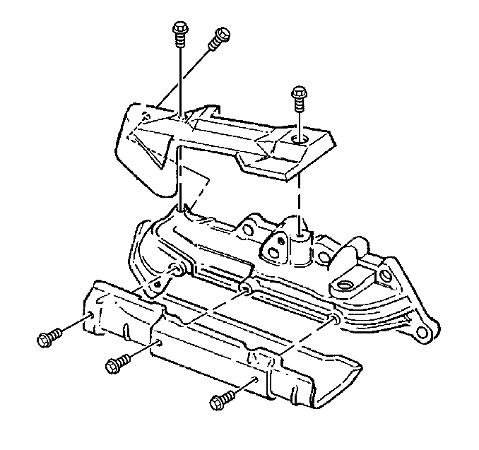
- Remove the three exhaust manifold lower heat shield bolts.
- Remove the exhaust manifold lower heat shield.
- Remove the exhaust manifold rear lower three nuts.
- Remove the rear, upper heat shield bolt.
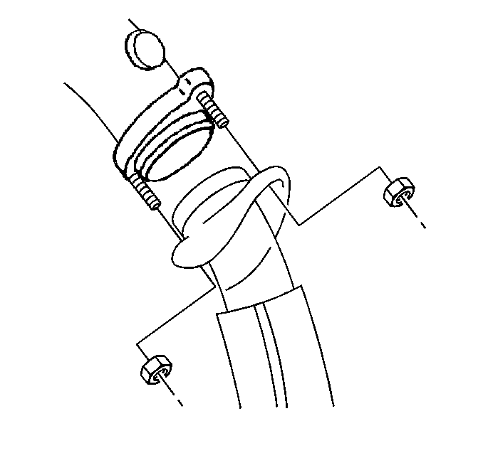
- Remove the catalytic converter nuts from the exhaust manifold.
- Lower the vehicle.
- Remove the serpentine drive belt tensioner. Refer to Drive Belt Tensioner Replacement .
- Remove the exhaust manifold front two nuts.
- Remove the exhaust manifold upper heat shield bolts. The upper heat shield stays in place. The bolts are removed to enable access to the AIR injection pipe.
- Remove the AIR injection pipe bolts (1).
- Remove the AIR injection pipe (2) from the exhaust manifold.
- Remove the exhaust manifold upper two nuts.
- Raise and support the vehicle. Refer to Lifting and Jacking the Vehicle in General Information.
- Remove the exhaust manifold.
- Clean the cylinder head mating surfaces.
- Clean the exhaust manifold mating surfaces if being reused.


Installation Procedure
- Install the exhaust manifold and hold in place with manifold nuts.
- Lower the vehicle.
- Install the exhaust manifold upper two nuts.
- Install the AIR injection pipe (2) to the exhaust manifold.
- Coat the AIR injection pipe bolts (1) with high temperature anti-seize compound, GM P/N 5613695 or equivalent.
- Install the AIR injection pipe bolts (1).
- Coat the exhaust manifold upper heat shield bolts with high temperature anti-seize compound, GM P/N 5613695 or equivalent.
- Install the exhaust manifold upper heat shield bolts.
- Install the exhaust manifold front lower two nuts.
- Install the serpentine drive belt tensioner. Refer to Drive Belt Tensioner Replacement .
- Raise and support the vehicle. Refer to Lifting and Jacking the Vehicle in General Information.
- Install the catalytic converter nuts to the exhaust manifold.
- Install the exhaust manifold rear lower three nuts.
- Install the exhaust manifold lower heat shield.
- Coat the exhaust manifold lower heat shield bolts with high temperature anti-seize compound, GM P/N 5613695 or equivalent.
- Install the exhaust manifold lower heat shield bolts.
- Lower the vehicle.
- Install the coolant intake pipe. Refer to Engine Coolant Inlet Pipe Replacement .
- Install the transmission. Refer to Transmission Assembly in Automatic Transmission.
Notice: Use the correct fastener in the correct location. Replacement fasteners must be the correct part number for that application. Fasteners requiring replacement or fasteners requiring the use of thread locking compound or sealant are identified in the service procedure. Do not use paints, lubricants, or corrosion inhibitors on fasteners or fastener joint surfaces unless specified. These coatings affect fastener torque and joint clamping force and may damage the fastener. Use the correct tightening sequence and specifications when installing fasteners in order to avoid damage to parts and systems.
Tighten
Tighten the exhaust manifold upper two nuts to 20 N·m (15 lb ft).

Tighten
Tighten the AIR injection pipe bolts to 20 N·m (15 lb ft).

Tighten
Tighten the exhaust manifold upper heat shield bolts to 8 N·m
(71 lb in).
Tighten
Tighten the exhaust manifold front lower two nuts to 20 N·m
(15 lb ft).

Tighten
Evenly tighten the catalytic converter nuts to 20 N·m (15 lb ft).
Tighten
Tighten the exhaust manifold rear lower three nuts to 20 N·m
(15 lb ft).
Tighten
Tighten the exhaust manifold lower heat shield bolts to 8 N·m
(71 lb in).
