Disassembly Procedure
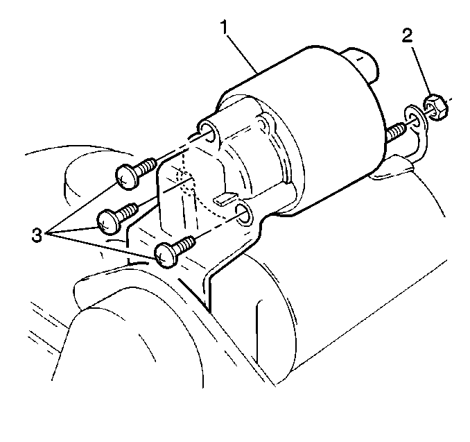
- Remove the starter solenoid
field coil lead:
| • | Remove the field coil nut (2) |
| • | Remove the field coil lead |
- Remove the solenoid screws (3).
- Remove the solenoid.
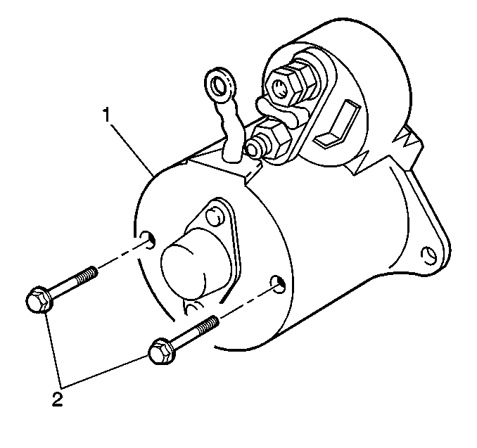
- Remove the commutator
end shield bolts (2).
- Remove the commutator end shield washers.
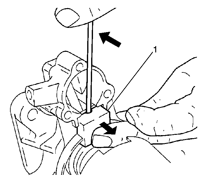
- Drive the shift lever
sealing plate (1) out of the armerature frame.
- Remove the shift lever plunger from the housing.
- Pry out the shift lever guide from the drive pinion housing.
- Remove the drive pinion housing.
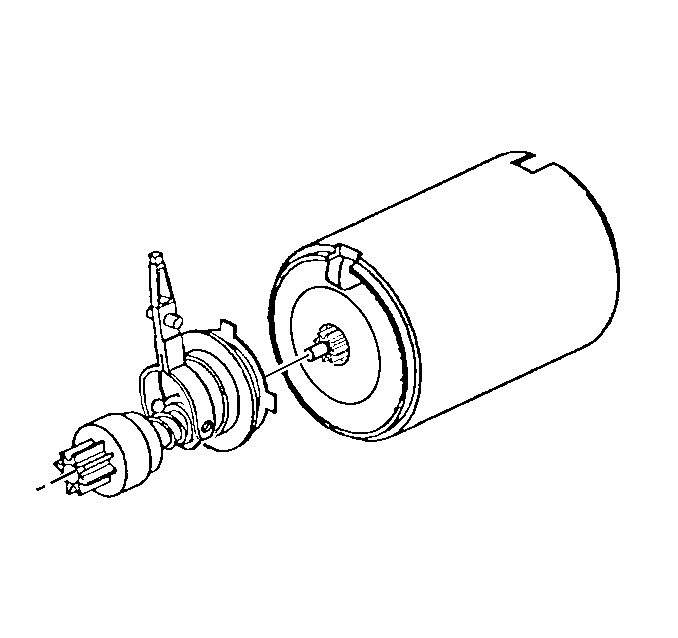
- Pull out the drive pinion
with the gear reduction unit.
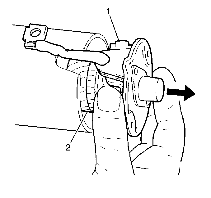
- Lightly tap on the armature
shaft in order to unseat the commutator end frame from the armature frame.
- Remove the armature with the commutator end frame and brush holder
(1) from the armature frame.
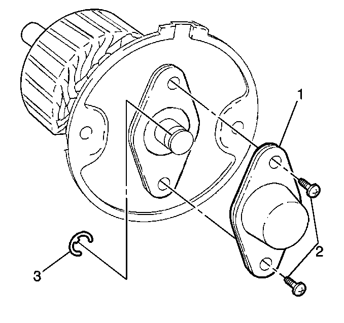
- Remove the commutator
end frame cover screws (2).
- Remove the commutator end frame cover (1).
- Remove the armature E clip (3).
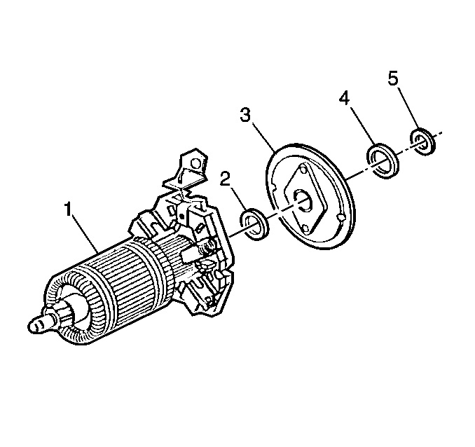
- Remove the following components
from the armature:
| • | The commutator end frame (3) |
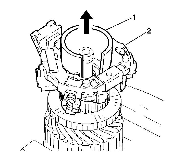
- Remove the brush holder
plate (2) using a piece of pipe or a socket (1) about 32.0 mm (1.25 in)
in order to retain the brushes in the plate.
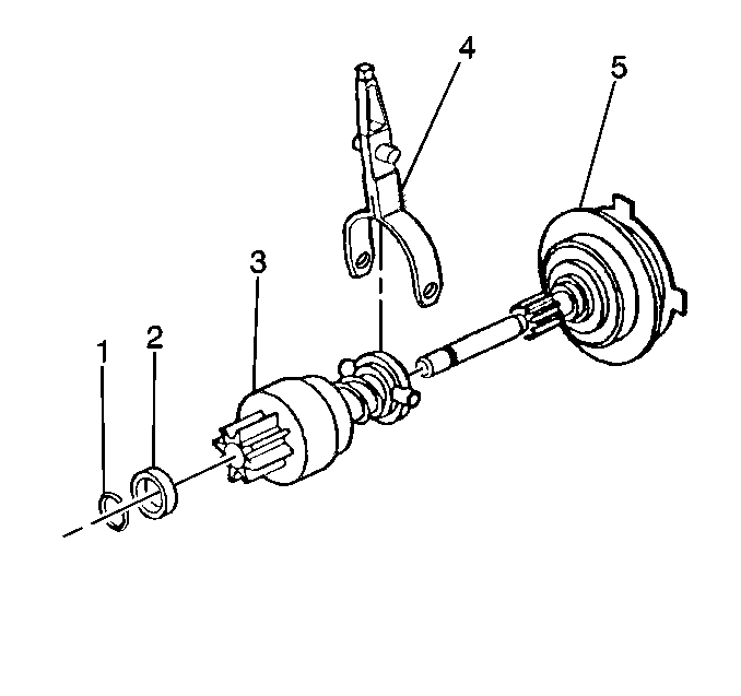
- Drive the collar from
the drive gear retainer using a deepwell 14 mm socket.
- Remove the retainer (1).
- Remove the collar (2) and the starter drive (3) from the gear
reduction unit.
- Seperate the shift lever legs in order to remove the lever from
the starter drive gear (4).
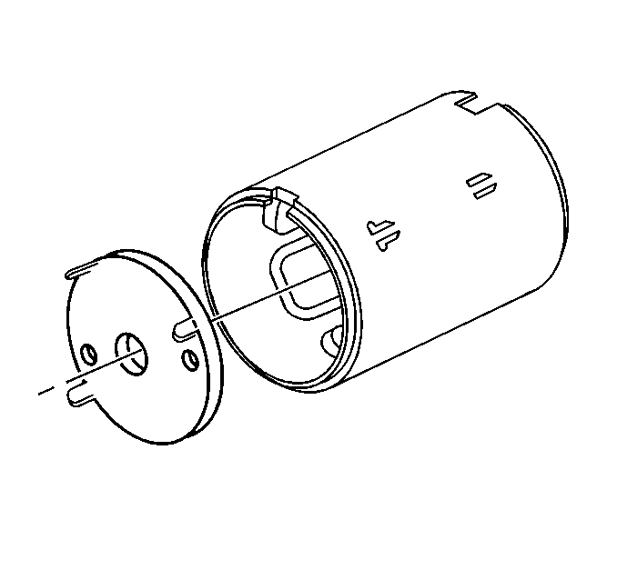
- Remove the gear reduction
unit shield from the housing.
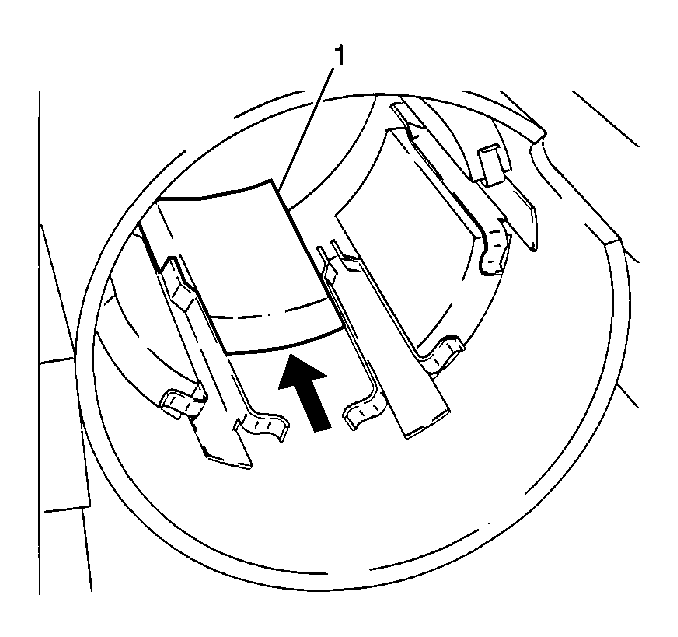
- Remove the field coils
(1) from the armature frame:
| • | Using a drift, drive the field coils rearward in order to remove. |
Cleaning, Inspection, and Testing Procedure
Notice: Do not use grease dissolving solvents for cleaning the overrunning clutch
or armature. Solvents dissolve the grease packed in the clutch and damage
the armature and the field coil insulation.
- Clean all starter motor parts, wiping dry with a clean shop cloth.
- Test the starter drive pinion:
| • | Inspect the action: the starter drive should turn freely in the
overrunning direction and lock up in the drive direction. |
| • | Inspect the teeth for any chips, cracks, or excessive wear: |
| - | Badly chipped teeth may indicate chipped flywheel teeth. |
| - | Replace the flywheel as needed. |
| • | Clean the pinion, but do not lubricate. |
- Inspect the armature commutator:
| • | Clean as needed using a 400 grit polishing cloth. |
| • | Machine the commutator surface of the armature if the surface
is rough. |
Specification
Commutator diameter (min.): 31.20 mm (1.228 in).
| • | Inspect the points where the conductors join the commutator bars
in order to ensure proper connections. (A burned commutator bar is usually
evidence of a poor connection.) |
- Inspect the brushes and the brush holders:
| • | Inspect the brush length. |
Specification
Brush length (min.): 8.00 mm (0.315 in)
| • | Inspect that the brush holders are clean and the brushes are not
binding in the holders. |
| • | Inspect the brush spring tension between the brushes and the commutator.
Replace the springs if distorted or discolored. |
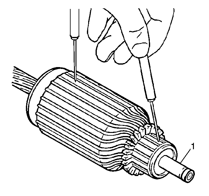
- Test the armature for
shorts:
| • | Place the armature on a growler. |
| • | Hold a hacksaw over the core while rotating the armature. |
| • | If the saw blade vibrates, the armature is shorted and must be
replaced. |
- Test the armature winding for a short to ground:
| • | Hold self powered test light probes to the core and the corresponding
commutator lamination. |
| • | If the test lamp lights, replace the armature. |
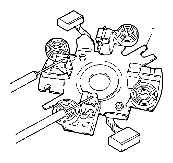
- Test the brush holder
(1) for a short:
| • | Using a self powered test light, hold the probes on the negative
and positive brush holders. |
| • | If the test lamp lights, replace the brush holder. |
Drive Gear Housing Bearing Replacement
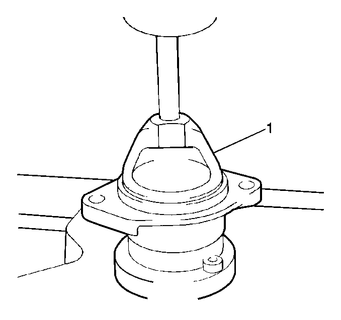
- Drive the bearing from
the housing (1) using a suitable drift.
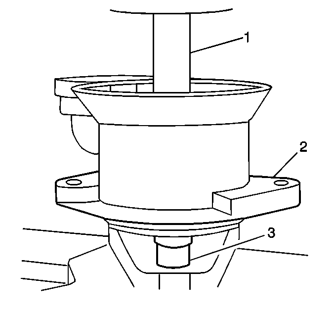
- Press the new bearing
into the housing (2) using a suitable size driver and a press.
Drive End Bushing Replacement
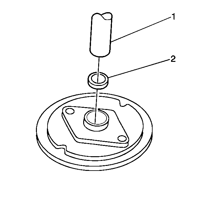
- Soak the new bushing (2)
in oil for at least 1/2 hour before installation.
- Place a suitable size socket under the housing.
- Use a suitable size driver (1) in order to drive the bushing from
the housing.
- Press in the new bushing using a suitable size driver and a press.
Assembly Procedure

- Install the field coils
(1) in the armature frame:
| • | Use a soft drift in order to seat the field coils in the armature
frame. |

- Install the gear reduction
unit shield to the armature frame.

- Seperate the shift lever
legs (4) in order to install the lever to the starter drive.
- Install the starter drive gear (3) and the retainer collar to
the gear reduction unit.
- Install the starter drive gear retainer.
- Snap the starter drive gear retainer collar onto the retainer
using a plastic tool.

- Install the brush holder
plate (2) to the armature using a piece of pipe or a socket (1) about 32.0 mm
(1.25 in) in order to retain the brushes.

- Install the following
components to the armature:

- Install the armature E
clip (3).
- Install the commutator end frame cover (1).
Notice: Use the correct fastener in the correct location. Replacement fasteners
must be the correct part number for that application. Fasteners requiring
replacement or fasteners requiring the use of thread locking compound or sealant
are identified in the service procedure. Do not use paints, lubricants, or
corrosion inhibitors on fasteners or fastener joint surfaces unless specified.
These coatings affect fastener torque and joint clamping force and may damage
the fastener. Use the correct tightening sequence and specifications when
installing fasteners in order to avoid damage to parts and systems.
- Install the commutator
end frame cover screws (2).
Tighten
Tighten the screws to 1.8 N·m (16 lb in).

- Install the armature with
the brush holder, lightly tap the brush holder (1) in order to seat in the
armature frame.

- Install the starter drive
gear with the gear reduction unit.
- Install the drive end frame.
- Push the shift lever guide into the drive end frame.
- Install the shift lever plunger to the solenoid housing.

- Push the shift lever sealing
plate (1) into the housing.

- Install the commutator
end washers.
- Install the commutator end bolts (2) to the starter motor.
Tighten
Tighten the bolts to 5 N·m (44 lb in).

- Install the solenoid.
- Install the solenoid screws.
Tighten
Tighten the screws to 5 N·m (44 lb in).
- Install the field coil lead to the solinoid.
- Install the field coil lead nut (2).
Tighten
Tighten the nut to 8 N·m (71 lb in).
- Bench test the starter operation.


