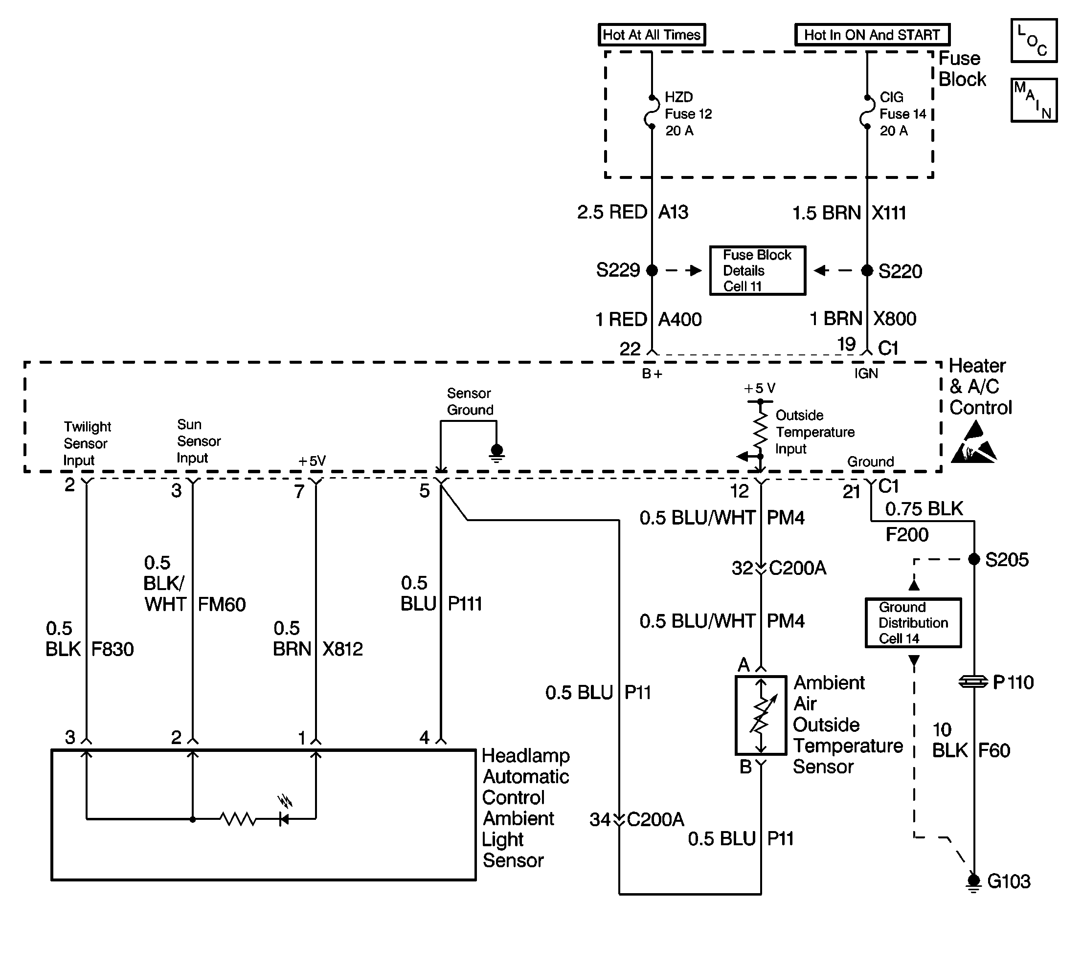
Circuit Description
The solar/twilight sensor is a photo-electric cell that provides two inputs to the heater and A/C control system. The input for the sunload is at terminal 3 of the heater and A/C control. This is used by the controller for temperature control compensation based on additional heat from the sun (sunload.) The input for the twilight sentinel is at terminal 2. This input is processed by the controller and sent to the Body Control Module (BCM).
Conditions for Setting the DTC
The heater and A/C control continuously monitors all circuits to the solar/twilight sensor every 200 ms. DTC 9 will set when the heater and A/C control detects an open in any of the three circuits or the sensor loses ground.
Action Taken When the DTC Sets
| • | Stores a DTC 9 in the heater and A/C control memory. |
| • | The system will default to a assumed value of no solar heat (darkness). |
Conditions for Clearing the DTC
| • | The conditions for the fault are no longer present. |
| • | Using a scan tool. |
| • | A history DTC will clear after 20 consecutive ignition cycles if the condition for the fault is no longer present. |
Diagnostic Aids
| • | If the DTC is a history or intermittent. Try performing the tests shown while moving the wiring harnesses and connectors, this can often cause the malfunction to appear. |
| • | When moving related harnesses and harness connectors, visually/physically inspect wiring and connectors for the following: |
| - | Wiring broken inside the insulation. This condition could cause a continuity check to show a good circuit, but if only one or two strands of a multi-strand type wire are intact, resistance could be far too high. |
| - | Poor mating of the connector halves or a terminal not fully seated in the connector body (backed out) |
| - | Improperly formed or damaged terminals. All connector terminals in the related circuits should be carefully reformed or replaced to insure proper contact tension. |
| - | Poor terminal to wire connection. Inspect for poor crimps, crimping over wire insulation rather than the wire. |
Test Description
The number(s) below refer to the step number(s) on the diagnostic table.
-
This step checks for available reference voltage from the heater and A/C control. Connecting a DMM in series checks the power and ground circuits at the same time. A normal reading is approximately 5.0 - 5.5 V. A significantly lower voltage reading indicates a circuit problem.
-
This step tests the other two circuits between the heater and A/C control and the solar/twilight sensor for an open circuit.
-
This step replaces the solar/twilight sensor. If no apparent circuit problem was found in the previous step, the most likely cause of the malfunction could be the solar/twilight sensor. The sensor can not be tested individually. Replacing the sensor is the only option.
-
If the DTC continues to reset after a repair or component replacement, the most likely cause is a failure internal to the heater and A/C control.
Step | Action | Value(s) | Yes | No |
|---|---|---|---|---|
1 | Was the Air Delivery System Check performed? | -- | Go to Air Delivery System Check | |
Is the voltage reading within the specified value? | 5.0-5.5 V | |||
Are both resistance readings within the specified value? | Less than 2 ohms | |||
4 | Move the negative lead of the DMM to another ground point and remeasure the voltage at terminal 1. Is the voltage reading within the specified value? | 5.0 - 5.5 V | ||
Replace solar/twilight sensor. Is the replacement complete? | -- | -- | ||
6 | Locate and repair the open circuit(s) that failed the resistance test. Is the circuit repair complete? | -- | -- | |
7 | Locate and repair open ground circuit (P111). Is the circuit repair complete? | -- | -- | |
8 |
Is the resistance reading within the specified value? | Less than 2 ohms | ||
Replace and program the heater and A/C control. Refer to Heater and A/C Control Replacement for the programming procedure. Is the replacement and programming complete? | -- | Go to Air Delivery System Check | -- | |
10 |
Is a current DTC 9 present? | -- | Go to Air Delivery System Check | |
11 | Locate and repair the open circuit in CKT X812. Is the circuit repair complete? | -- | -- |
