Brake Caliper Replacement Front
Removal Procedure
- Raise and suitably support the vehicle. Refer to
Lifting and Jacking the Vehicle
.
- Remove the tire and the wheel. Refer to
Wheel Removal
in Tires and Wheels.
- Carefully separate sensor from the inner brake pad by placing
a small screwdriver between the lower section of the sensor and the brake
pad and apply mild twisting force to screwdriver.
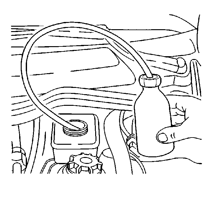
- Remove two thirds of the
fluid from the master cylinder reservoir.
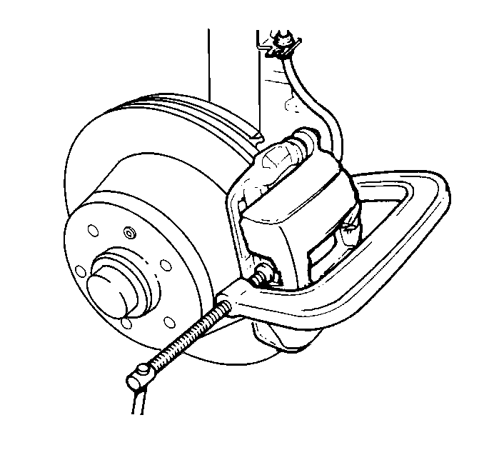
- Compress piston into caliper
housing bore to provide clearance between linings and rotor.
| • | Ensure one end of C-clamp rest on brake hose fitting bolt and
the other end against the outer pad. |
| • | Tighten C-clamp slowly to press piston into caliper housing bore. |
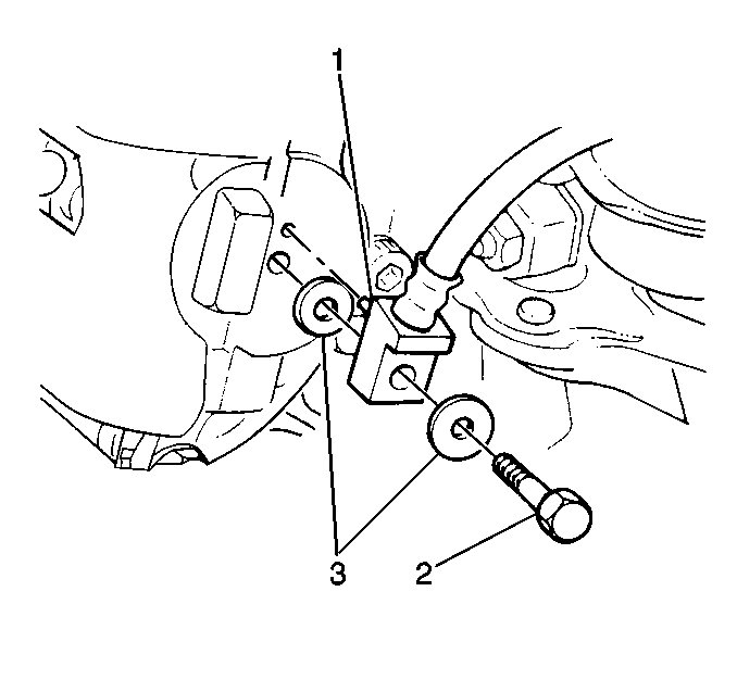
- Remove the following components
if the caliper is being serviced or replaced:
| • | Remove the front brake hose bolt (3) |
| • | Remove the front brake hose (1) |
| • | Remove the front brake hose seals (2) |
- Discard bolt and seals.
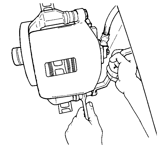
- Remove the guide pin bolts
(discard bolts).
- Remove the caliper from the caliper bracket.
Suspend with mechanic's wire if necessary.
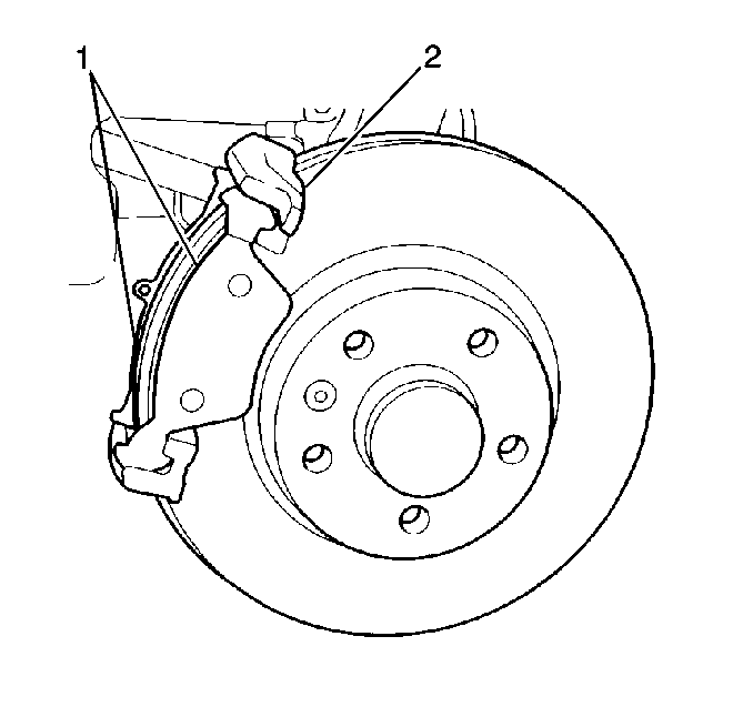
- Remove the inner and outer
pads (1) from the caliper bracket (2).
- Inspect the inner and outer pads for wear and maximum taper of
0.15 mm (0.006 in). Replace with a new brake pad set if they
are tapered beyond specification.
Caliper Disassemble Procedure
- Disassemble the piston from housing.
| • | Insert piece of wood or shop towel into caliper to cushion piston
upon removal. |
| • | Apply moderate compressed air to the caliper housing inlet hole. |
- Inspect the piston for the following conditions:
| • | Worn or damaged chrome plating |
| • | Replace the piston if any of the above are found. |
- Disassemble the front brake caliper dust boot from housing.
- Disassemble the front brake caliper seal (1) from the housing.
Use a small wood or plastic tool.
- Insect the caliper housing bore and seal groove for the following
conditions:
| 1. | Use crocus cloth to polish out light corrosion. |
| 2. | Replace caliper if corrosion in and around the seal groove will
not clean up with crocus cloth. |
Caliper Assemble Procedure
- Clean all parts in denatured alcohol.
- Dry with unlubricated compressed air.
- Blow out all passages in housing and valve with compressed air.
- Lubricate piston and all rubber parts with clean brake fluid.
- Seal into the bore groove of housing.
Ensure seal is seated and not twisted.
- Dust boot (2) into caliper housing (3).
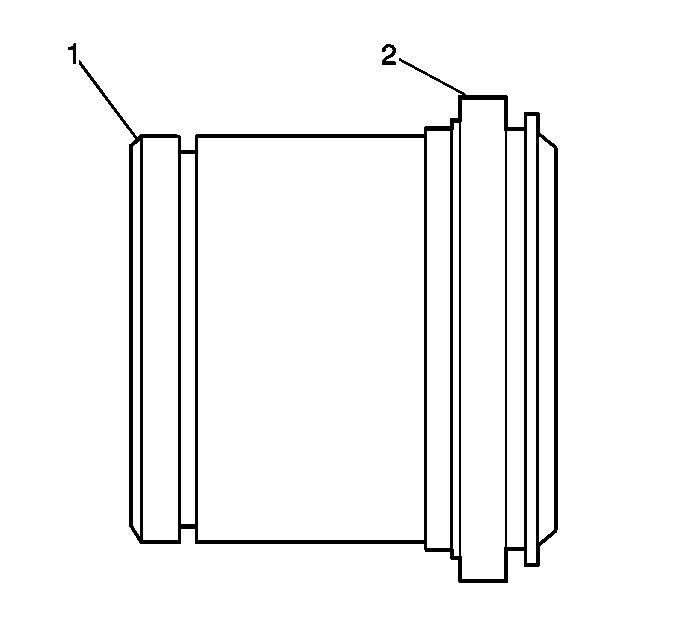
- Assemble piston (1) into dust boot (2).
- Push piston to the bottom of the caliper housing
bore.
Important: By applying compressed air to the caliper housing inlet bore and positioning
the piston in front of the dust boot the compressed air will expand the boot
over the piston. Once the boot is over the piston release the compressed
air and insert the piston into the bore. This may require assistance of a
helper.
Important: Once the piston is bottomed into the caliper housing bore the dust boot
will seat itself in the machined channel on the piston. Caliper is now ready
for installation.
Installation Procedure
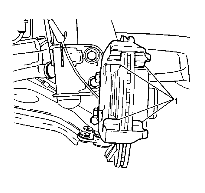
- Ensure the front brake
caliper bracket mounting surfaces (1) are clean and lubricated.

- Install the inner and
outer pads (1) into caliper bracket (2), if removed.
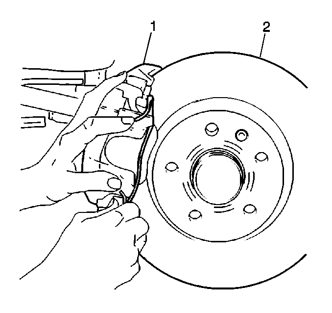
- Install the caliper (1).
- Install the brake pad sensor.

Notice: Use the correct fastener in the correct location. Replacement fasteners
must be the correct part number for that application. Fasteners requiring
replacement or fasteners requiring the use of thread locking compound or sealant
are identified in the service procedure. Do not use paints, lubricants, or
corrosion inhibitors on fasteners or fastener joint surfaces unless specified.
These coatings affect fastener torque and joint clamping force and may damage
the fastener. Use the correct tightening sequence and specifications when
installing fasteners in order to avoid damage to parts and systems.
- Install new guide
pin bolts.
Tighten
Tighten guide pin bolts to 30 N·m (22 lb ft).
- Install the front brake hose if removed.
- Install new seals if removed.
- Install a new front brake hose bolt if removed.
Tighten
Tighten the front brake hose bolt to 40 N·m (30 lb ft).
- Bleed brake hydraulic system. Refer to
Hydraulic Brake System Bleeding
in Hydraulic Brakes.
- Install the tire and wheel. Refer to
Wheel Installation
in Tires and wheel.
- Lower the vehicle.
Brake Caliper Replacement Rear
Removal Procedure
- Remove the rear disc brake pads. Refer to
Brake Pads Replacement
.
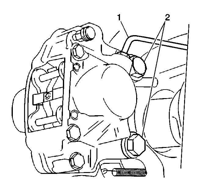
- Remove the rear brake
caliper pipe (1).
- Remove the rear brake caliper bolts (2).
- Remove the rear brake caliper from the rotor.
Important: It is not necessary to separate the caliper housing halves to overhaul
the cylinders. Replace the caliper if the housing leaks from the mating surfaces.
Disassemble Procedure
Tool Required
J 22429 Piston Retainer
- Install the J 22429 Piston Retainer onto the caliper opposite
the cylinder to be removed.
- Direct dry, filtered compressed air into the fluid channel port
of the caliper housing to remove the piston.
Caution: Do not place your fingers in front of the piston in order
to catch or protect the piston while applying compressed air. This could result
in serious injury.
Important: Use clean shop towels to pad the inside of the caliper housing during
the rear brake caliper piston removal.
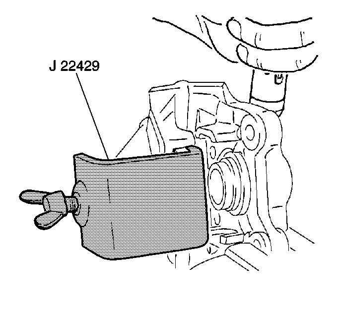
- Use the J 22429
Piston Retainer to cover the exposed bore.
- Use dry unlubricated compressed air to carefully remove the opposing
piston.
Caution: Do not place fingers in front of the caliper piston(s) in an attempt
to catch or protect it when applying compressed air. The piston(s) can fly
out with force and could result in serious bodily injury.
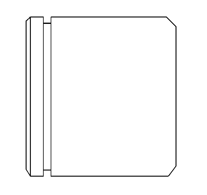
- Inspect the pistons for
the following conditions:
- Replace the piston(s) as necessary.
- Use a small wood or plastic tool to remove the rear brake caliper
piston seal(s).
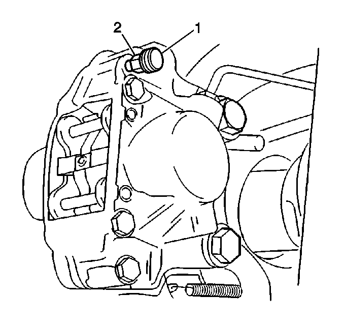
- Remove the bleeder valve
cap (1).
- Remove the rear brake caliper bleeder valve (2).
- Discard the bleeder valve.
- Inspect all the parts for the following conditions:
| • | Inspect for excessive wear. |
| • | Inspect for other changes. |
- Replace the parts as necessary.
- Use denatured alcohol to clean all the parts not included in the
repair kit.
- Use dry, filtered compressed air to dry the parts.
- Blow out all the passages in the caliper housing.
- Blow out all the passages in the bleeder valve.
- Inspect the caliper housing bores for the following conditions:
- Replace the caliper housing if badly scored and/or corroded around
the seal areas.
Assemble Procedure

- Install a new bleeder
valve (2).
- Install a new bleeder valve cap (1).
- Use clean brake fluid to lubricate the new piston seals.
- Use clean brake fluid to lubricate the caliper housing bore seal
grooves.
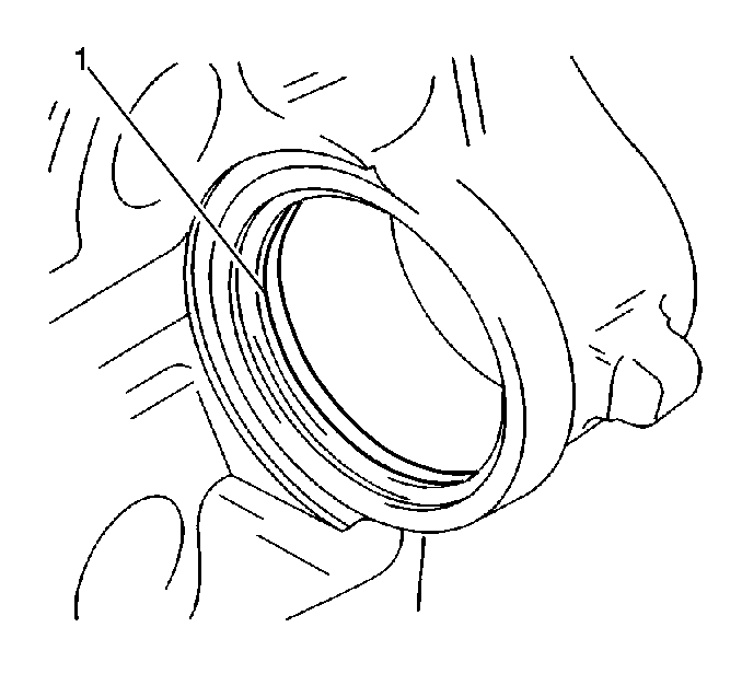
- Install new piston seals
(1) into the caliper
housing seal grooves.
Important: Ensure the piston seals are properly seated and not twisted.
- Use clean brake fluid to lubricate the bores of the caliper housing.
- Use clean brake fluid to lubricate the pistons.

- Install the dust boots
(2) onto the pistons (1).
The dust boot seats in the piston channel once the piston is fully seated.
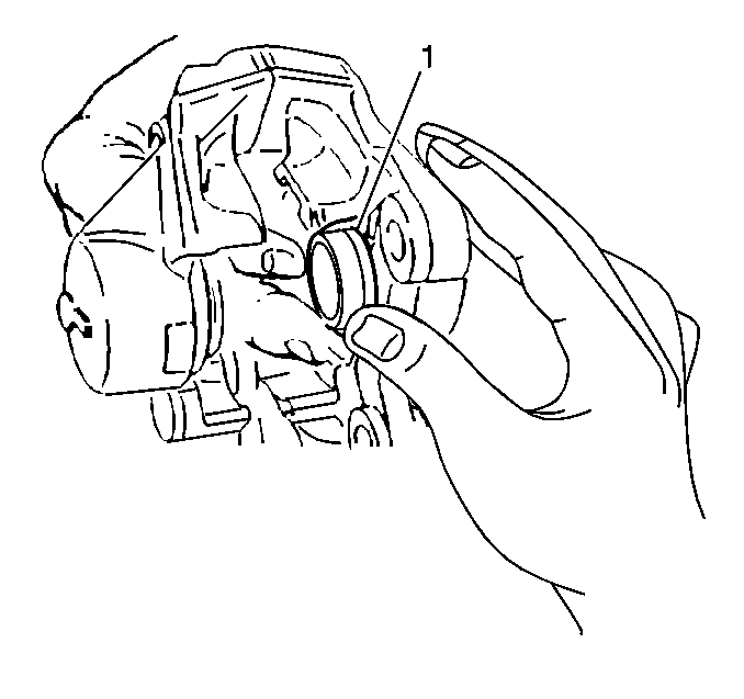
- Push the pistons down
by hand into the bottom
of the bores of the caliper housing.
- Work the outer edge of the dust boots around the caliper housing
embossments (1) with the pistons bottomed in the bores.
- The caliper is now ready for reinstallation.
Installation Procedure
- Install the caliper onto the rotor.

- Install the rear brake
caliper bolts (2).
Notice: Use the correct fastener in the correct location. Replacement fasteners
must be the correct part number for that application. Fasteners requiring
replacement or fasteners requiring the use of thread locking compound or sealant
are identified in the service procedure. Do not use paints, lubricants, or
corrosion inhibitors on fasteners or fastener joint surfaces unless specified.
These coatings affect fastener torque and joint clamping force and may damage
the fastener. Use the correct tightening sequence and specifications when
installing fasteners in order to avoid damage to parts and systems.
Tighten
Tighten the rear brake caliper bolts (2) to 80 N·m (59 lb ft).
- Install the rear brake caliper pipe (1) to the caliper.
Tighten
Tighten the brake pipe fitting to 16 N·m (12 lb ft).
- Install the rear disc brake pads. Refer to
Brake Pads Replacement
.
- Install the tire and wheel assembly. Refer to
Wheel Installation
in Tires and Wheels.
- Lower the vehicle.
- Bleed the brake hydraulic system. Refer to
Hydraulic Brake System Bleeding
in Hydraulic Brakes.


